Blog Entry
Introduction to the Microchip PIC C Programming
December 18, 2008 by rwb, under Microcontroller.
The PIC microcontroller is quite popular in industrial and hobbyist, some of the newest 8-bit midrange Microchip PIC microcontroller with nanoWatt technology is PIC16F690, this 20 pin microcontroller has a build in peripherals such as ADC, UART, PWM, I2C, analog comparator and with 7KBytes program memory flash; for those who’s come from the AVR background this is a good change to gain the knowledge as we know is hard to find the comparable 20 pin 8-bit AVR microcontroller product which has the same feature as Microchip PIC16F690; and for those who are the first time learner welcome to the PIC microcontroller world.
1. Which tools should I use
To start C programming language on Microchip PIC Microcontroller you need these following tools:
- Down load the latest Microchip MPLAB IDE which provide you with the complete IDE (integrated development environment) for managing project, program editing, compiling, debugging and downloader for all Microchip PIC Microcontroller series.
The MPLAB IDE is already come with the HITECH PICC-Lite C compiler and fully integrated with MPLAB IDE. - The PIC16F690 datasheet, is one of the most important document if you want to learn this type of microcontroller
- Microchip PICKit2 Programmer.
- PICJazz 16F690 board from ermicro (for circuit schema click here)
After downloading, install the Microchip MPLAB IDE and just follow all the default setting.
2. My first PIC C Programming
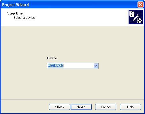
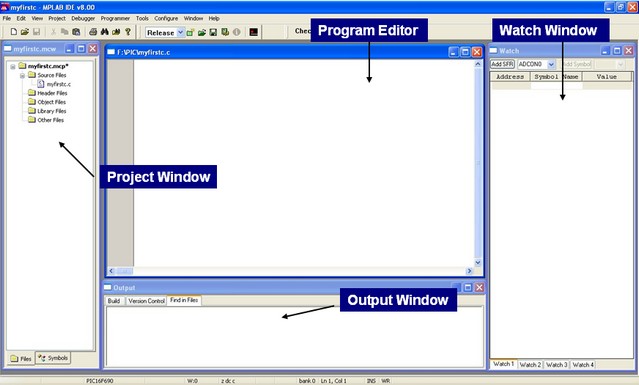
To create your first PIC project go to Start -> All Programs -> Microchip -> MPLAB IDE ver 8.00 -> MPLAB IDE (I am using version 8.00 on this tutorial), this will launch the MPLAB IDE application screen then start the project wizard by selecting the menu Project -> Project Wizard… from MPLAB IDE and this will launch the project wizard, just continue with Next button and it will show the project wizard step one form as follow:
Choose the PIC16F690 device then click Next button:
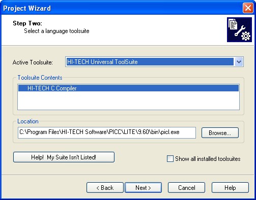
On step two we choose the HI-TECH C Compiler and click Next button
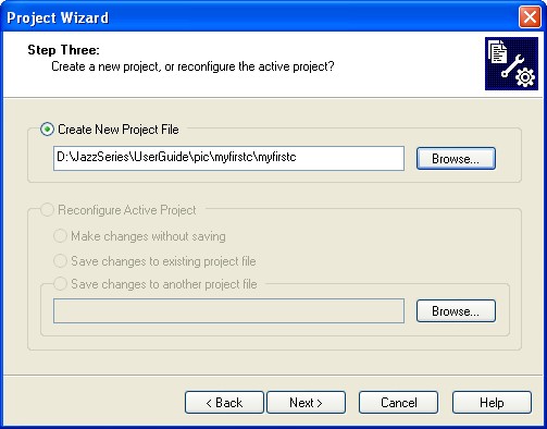
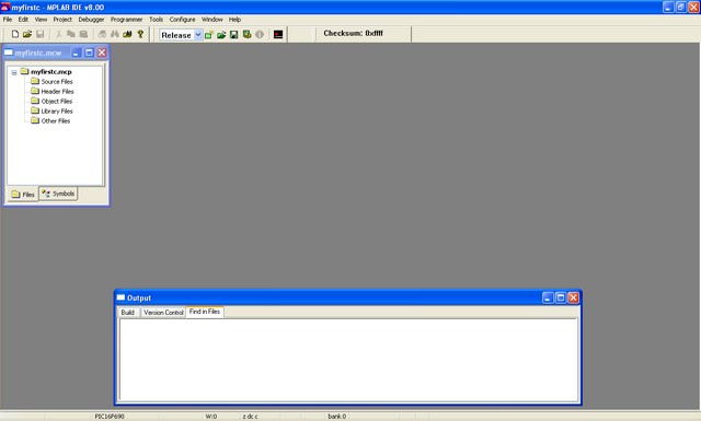
Step three create your project file which is myfirstc in this tutorial then click Next button; on step four just click Next button because this is you first program there is no existing file to be added then press Finish button on the last screen; this will bring you to the MPLAB IDE blank environment as follow:
From MPLAB IDE create new program file by selecting menu File -> New and save it as myfirstc.c using menu File -> Save As. Again from MPLAP IDE menu select View than activate the Project, Output and the Watch screen. On the project screen right click on the Source Files and chose Add Files…; add myfirst.c file into the project as shown on this following picture:
Now you are ready to start your first PIC C program, just copy and paste this following code:
/*************************************************************************
**  File Name    : myfirstc.c
**  Version      : 1.0
**  Description  : My First PIC C Programming
**  Author(s)    : RWB
**  Target(s)    : PICJazz 16F690 Board
**  Compiler     : HITECT PICC-Lite Version 9.60PL1
**  IDE          : Microchip MPLAB IDE v8.00
**  Programmer   : PICKit2
**  Last Updated : 08 Dec 2008
*************************************************************************/
#include <pic.h>
/*   PIC Configuration Bit:
**   INTIO     - Using Internal RC No Clock
**   WDTDIS    - Wacthdog Timer Disable
**   PWRTEN    - Power Up Timer Enable
**   MCLREN    - Master Clear Enable
**   UNPROTECT - Code Un-Protect
**   UNPROTECT - Data EEPROM Read Un-Protect
**   BORDIS    - Borwn Out Detect Disable
**   IESODIS   - Internal External Switch Over Mode Disable
**   FCMDIS    - Monitor Clock Fail Safe Disable
*/
__CONFIG(INTIO & WDTDIS & PWRTEN & MCLREN & UNPROTECT & UNPROTECT & BORDIS & IESODIS & FCMDIS);
/* Using Internal Clock of 8 Mhz */
#define FOSC 8000000L
/* The Delay Function */
#define	delay_us(x) { unsigned char us; \
		      us = (x)/(12000000/FOSC)|1; \
		      while(--us != 0) continue; }
void delay_ms(unsigned int ms)
{
  unsigned char i;
  do {
    i = 4;
    do {
      delay_us(164);
    } while(--i);
  } while(--ms);
}
void main(void)
{
  OSCCON=0x70;         /* Select 8 Mhz internal clock */
  TRISC = 0x00;	       /* Set All on PORTC as Output */
  ANSEL = 0;           /* Set PORT ANS0 to ANS7 as Digital I/O */
  ANSELH = 0;          /* Set PORT ANS8 to ANS11 as Digital I/O */
  for(;;) {
    PORTC = 0x01;      /* Turn On Port RC0 */
    NOP();
    delay_ms(200);     /* Delay 200 ms */
    PORTC = 0x00;      /* Turn Off Port RC0 */
    NOP();
    delay_ms(200);     /* Delay 200 ms */
  }
}
3. The PIC microcontroller C Code
One of the interesting part in Microchip PIC microcontroller feature is the configuration bit, this bit can be set when we power on the microcontroller and put it in our program; unlike AVR microcontroller which known as fuse bit and lock bit; this bits has to be set first before we can use the microcontroller. You could include this setting on your code or instruct the MPLAB IDE to include this setting for you by using menu Configure -> Configuration Bits as follow:
Uncheck the Configuration Bits set in code option and this setting will overwrite any configuration bit you set in your code. For this tutorial I am using this configuration bit statement (remember using CONFIG with double underscore):
__CONFIG(INTIO & WDTDIS & PWRTEN & MCLREN & UNPROTECT & UNPROTECT & BORDIS & IESODIS & FCMDIS);
Now let’s take a look in the main() code area; the first statement is to choose the 8 Mhz internal clock, the default value is 4 Mhz and by setting the oscillator control register (OSCCON – special function register in the PIC16F690 microcontroller) to hex value 0x70 we choose the 8 Mhz internal clock (maximum) as follow:
OSCCON=0x70; /* Select 8 Mhz internal clock */
The TRISC is a three state bidirectional buffer control register for PORTC, by clearing all the bit (set to logical 0), we instruct the PIC microcontroller to use the PORTC as output port (by setting to logical 1 mean we use for input port).
TRISC = 0x00; /* Set All on PORTC as Output */
The ANSEL and ANSELH are the analog select registers; by default all the analog port in PIC16F690 are set to analog input not for digital I/O, therefore by clearing all bits (set to logical 0) in these special function registers we instruct the PIC microcontroller to use all the available analog input as a digital I/O port. This is one of important preparation before we use the PIC port for digital I/O:
ANSEL = 0;         /* Set PORT ANS0 to ANS7 as Digital I/O */
ANSELH = 0;        /* Set PORT ANS8 to ANS11 as Digital I/O */
Inside the empty for statement (never ending loop) I just assign the PORTC so the LED attached to RC0 on the PICJazz 16F690 board will on and off and put the delay 200 ms function between them, so we could see the process physically:
PORTC = 0x01;      /* Turn On Port RC0 */
NOP();
delay_ms(200);     /* Delay 200 ms */
PORTC = 0x00;      /* Turn Off Port RC0 */
NOP();
delay_ms(200);     /* Delay 200 ms */
The NOP() instruction is just the no operation instruction for PIC microcontroller, this function is used for setting the break point in the MPLAB IDE simulation before we download the code to the PICJazz 16F690 board. You can always use this NOP() function as many as you like to set the break point as this instruction will not effecting your code and removing it later.
4. Simulating your code
Debugging your code before burning it to the microcontroller is the essential part in developing embedded system; using the sophisticated Microchip MPLAB IDE simulation will give you a deep walk through to your code and watch how the PIC microcontroller responding to your code. The good part is; you don’t have to use any physical microcontroller to use this simulation tool, just your computer and of course the Microchip MPLAB IDE. Ok let’s start setting the environment before we start the simulation.
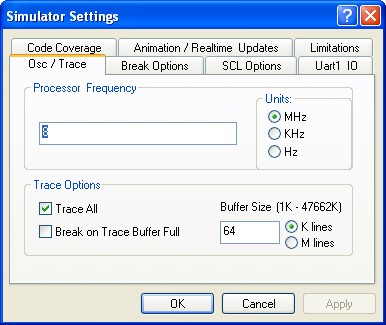
From MPLAB IDE menu select Debugger -> Select Tool -> MPLAB Sim; then again from menu select Debugger -> Setting…; this will bring you to the simulator setting form:
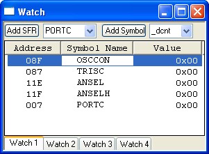
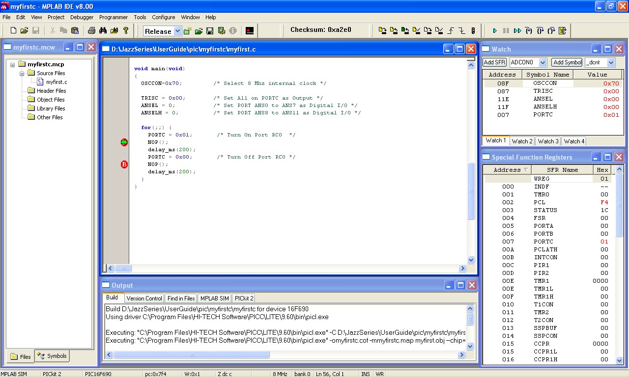
Set the Processor Frequency to 8 Mhz and leave the other setting to it’s default. Now on the Watch window add the special function registers to be observed e.g. OSCCON, TRISC, ANSEL, ANSELH and PORTC by selecting the register in the selection list and click the Add SFR button as follow (to remove it, right click on the highlighted register and choose delete):
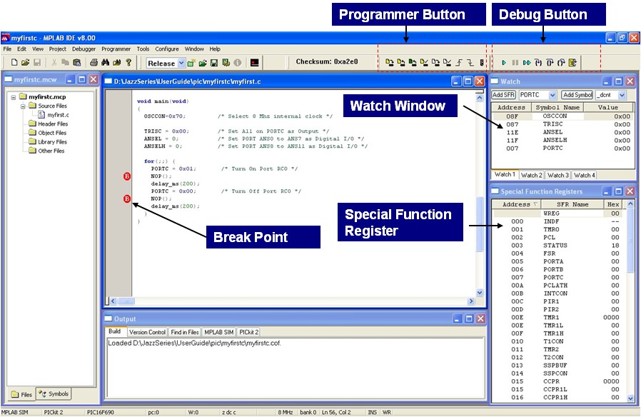
You could also watch all the special function register by activating the special function register window, from menu select View -> special function registers.
Now set the break point by putting the cursor on the first NOP() function and right click -> Set Break Point, the break point sign will appear on your editor screen and do the same thing on the second NOP() function. Now you are ready to compile your code, from menu select Project -> Build or press F10:
If everything’s smooth you will get no error message (if not check and recheck your code) and now you are ready to run the Microchip MPLAB ID simulation; from menu select Debugger -> Run or press F9:
You can look on your watch windows the PIC16F690 registers change by continuing press the F9 key. To reset the program, from menu select Debugger -> Reset -> Processor Reset or press the F6 key.
5. Downloading your code
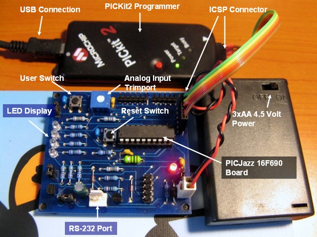
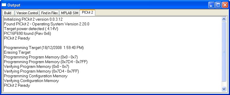
The final step is to put your code in a real PIC16F690 microcontroller, connect the PICkit2 programmer to the USB port and the programmer ICSP port to the PICJazz 16F690 board ICSP port; turn the PICJazz 16F690 power. From the MPLAB IDE menu select Programmer -> Select Programmer -> Pickit2 it will automatically configure the connection and display it on the PICkit2 tab Output windows:
Now you are ready to down load the code from MPLAB IDE menu select Programmer -> Program; this will down load the HEX code into the PICJazz 16F690 board:
Disconnect the ICSP port from the board and watch the LED blink.
Bookmarks and Share


Related Posts
29 Responses to “Introduction to the Microchip PIC C Programming”
Comment by rwb.
Make sure you are using the latest HITECH PICC Compiler and the Microchip MPLAB, when you install it correctly the pic.h file will be automatically recognized by the MPLAB IDE. Before you compile, check your language tool suite on MPLAB IDE: Project -> Select Language Toolsuite and make sure you select the HI-TECH Universal ToolSuite.
Comment by p4n4k4ts.
Nice work! Your posts are very helpful!
I am facing a problem and I would like to ask for some help! When I copied the code to the MPLAB IDE and tried to build the code, I got an error message about the “__CONFIG(INTIO & WDTDIS & PWRTEN & MCLREN & UNPROTECT & UNPROTECT & BORDIS & IESODIS & FCMDIS); ” command.
The error message was:
Error [800] C:\Users\katsa\Desktop\mplab projects\test005_pic16f690_myfirstc\myfirstc.c; 26. undefined symbol “FCMDIS”
Error [800] C:\Users\katsa\Desktop\mplab projects\test005_pic16f690_myfirstc\myfirstc.c; 26. undefined symbol “IESODIS”
Error [800] C:\Users\katsa\Desktop\mplab projects\test005_pic16f690_myfirstc\myfirstc.c; 26. undefined symbol “BORDIS”
Error [800] C:\Users\katsa\Desktop\mplab projects\test005_pic16f690_myfirstc\myfirstc.c; 26. undefined symbol “UNPROTECT”
Error [800] C:\Users\katsa\Desktop\mplab projects\test005_pic16f690_myfirstc\myfirstc.c; 26. undefined symbol “MCLREN”
Error [800] C:\Users\katsa\Desktop\mplab projects\test005_pic16f690_myfirstc\myfirstc.c; 26. undefined symbol “PWRTEN”
Error [800] C:\Users\katsa\Desktop\mplab projects\test005_pic16f690_myfirstc\myfirstc.c; 26. undefined symbol “WDTDIS”
Error [800] C:\Users\katsa\Desktop\mplab projects\test005_pic16f690_myfirstc\myfirstc.c; 26. undefined symbol “INTIO”
When I erased this configuration command, everything worked fine, except the fact that the configuration bits were missing.
Do you know what’s the problem or what am I doing wrong?
Thank you for your time! Keep uploading interesting projects!!!
Comment by rwb.
Thank you! Make sure you install the Microchip HI-TECH C Compiler for PIC10/12/16 MCUs (Lite Mode) V9.80 or above correctly and check your MPLAB IDE C compiler setting. From the MPLAB IDE menu choose Project -> Select Language Toolsuite, and on the ToolSuite Contents choose HI-TECH ANSI C Compiler (default installation location: C:\Program Files\HI-TECH Software\PICC\9.80\bin\picc.exe). Next try to recompile your code.
Comment by ppaul.
Hey. nice cod . I have tried this cod and the compiler give the same error from the user p4n4k4ts. I comment the line whit config and works ;).
You make good cod example . Thanks
Comment by rwb.
Thank you. See my answer at point #4. If you install the Microchip HI-TECH C compiler correctly than all the configuration bit definition needed for PIC16F690 will be in C:\Program Files\HI-TECH Software\PICC\9.80\include\pic16F685.h header file as follow:
// Configuration Mask Definitions
#define CONFIG_ADDR 0x2007
// Oscillator
#define EXTCLK 0x3FFF // External RC Clockout
#define EXTIO 0x3FFE // External RC No Clock
#define INTCLK 0x3FFD // Internal RC Clockout
#define INTIO 0x3FFC // Internal RC No Clock
#define EC 0x3FFB // EC
#define HS 0x3FFA // HS
#define XT 0x3FF9 // XT
#define LP 0x3FF8 // LP
// Watchdog Timer
#define WDTEN 0x3FFF // On
#define WDTDIS 0x3FF7 // Off
// Power Up Timer
#define PWRTDIS 0x3FFF // Off
#define PWRTEN 0x3FEF // On
// Master Clear Enable
#define MCLREN 0x3FFF // MCLR function is enabled
#define MCLRDIS 0x3FDF // MCLR functions as IO
// Code Protect
#define UNPROTECT 0x3FFF // Code is not protected
#define CP 0x3FBF // Code is protected
#define PROTECT CP //alternate
// Data EE Read Protect
#define UNPROTECT 0x3FFF // Do not read protect EEPROM data
#define CPD 0x3F7F // Read protect EEPROM data
// Brown Out Detect
#define BORDIS 0x3CFF // BOD and SBOREN disabled
#define SWBOREN 0x3DFF // SBOREN controls BOR function (Software control)
#define BORXSLP 0x3EFF // BOD enabled in run, disabled in sleep, SBOREN disabled
#define BOREN 0x3FFF // BOD Enabled, SBOREN Disabled
// Internal External Switch Over Mode
#define IESOEN 0x3FFF // Enabled
#define IESODIS 0x3BFF // Disabled
// Monitor Clock Fail-safe
#define FCMEN 0x3FFF // Enabled
#define FCMDIS 0x37FF // Disabled
Comment by ppaul.
Hey. I use the pic16f886 and i find the *.h for him . My questions
is to no write this part of cod in mplab with __Config… because is in file .h ?
Thanks
Comment by rwb.
The “undefined symbol” error message when compiling the C code on MPLAP IDE is due to wrong compiler setup and configuration.
When you use the Microchip HI-TECH C Compiler you only need to use the include “pic.h” header, because the compiler will automatically set the correct header for the default device selected (microcontroller) when you first start the project wizard. You could check or change the selected device in MPLAB IDE Configure -> Select Device menu.
You could see the example of using the Microchip PIC16F886 microcontroller C code on “Seven Segment Display Thermometer with PIC Microcontroller” project on this blog
Comment by p4n4k4ts.
Please allow me to join your discussion. What I found is that when I downgraded from MPLAB 8.66 (I think it is the latest version) to MPLAB 8.50 everything worked fine!!!
I also use HI-TECH C COMPILER 9.81
@ppaul : Try to install a previous version of MPLAB and inform us about the result
With regards,
p4n4k4ts
Comment by rwb.
The code should be compiled with the new version of Microchip MPLAB IDE v8.66 and HI-TECH C Compiler v9.80 correctly. The original project is compiled with MPLAB v8.00 and HI-TECH C Compiler v9.60. Currently I used Microchip MPLAB IDE v8.63 and HI-TECH C Compiler v9.80.
@p4n5k4ts: You could try to upgrade back to Microchip MPLAB IDE v8.66 with HI-TECH C Compiler v9.80 and see if it work.
Comment by ppaul.
I have the v 9.81 of HI TECH c Compiler and the Mplab v 8.66.
I write the program with the line comment of __Config …. , and it’s fine. Sometimes when i debugging whit PIC kit2 , the code is write in the microcontreler and when I do the F9 and F7 say and error “PK2Error0030: Failed to read target file registers” and i puts the breakpoints to stay . Sometimes work and sometimes no .
I use a sensor QRE 1113, have you a tutorial with them sensor.
I work this project for my final college ( the license). I must controlled a chassis whit tracked 2 * DC Motor and with 6 * sensor Sharp 2D120X , 3 * sensor Sharp 2Y0A21 , 2*sensor QRE 1113 and 1 * senzor LV-MaxSonar-EZ0. Plus a communication with PC and robot .
Thanks
Comment by rwb.
The QRE1113 is the infrared reflected sensors (i.e. infrared LED and Photo Transistor). Similar to QRE1113 this following article show how I used the infrared reflected sensors to track the black line on the Line Follower Robot:
Build Your Own Microcontroller Based PID Control Line Follower Robot (LFR) – Second Part
Comment by ppaul.
hey . I have a problem when I debugging with PicKit 2 . I compile the program and when I run the debugg with F9 and put the breakpoints in program , in output of PicKit2 is write a error how say:
”
Stepping Target
PICkit 2 Ready
PK2Error0030: Failed to read target file registers
”
I can not debugging line to line , give this error.
You can explain me ?
Thanks
Comment by rwb.
There are two method to debug your code in Microchip MPLAB IDE, the first one is to use the MPLAB Simulation (without PICKit2, menu Debugger -> Select Tool -> MPLAB SIM) and the second one is to use the “In Circuit Debugger” (with PICKit2). Remember not all the Microchip PIC microcontroller have “In Circuit Debugger” feature (read the datasheet).
Comment by ppaul.
In the Special Microcontroller Features of the data sheet pic16f886 is say “In-Circuit Debugger (on board)” . When i instal the first time the mplab ,and degguing your program from her , it’s work the debugging. and other cod it’s works but later become this error .
And I stay with the cod and can not debugging 🙁
Comment by ppaul.
With MPLAB SIM it’s work fine , but I need to see in real the input and output of my pin . For example , now i need to see the data when i trasnmit from serial port. I transmit from a application create in Visual C# through a Easy-Radio Transmiter ER400TS.
Comment by rwb.
The Microchip PIC16F886 microcontroller doesn’t has the “In Circuit Debugger (ICD) via Two Pins” feature, it require special external board in order to debug the PIC16F886 microcontroller with this method.
To understand the different please read the Microchip PIC18F24J11 (advanced 8-bit, 28-pin, 16KB flash) microcontroller datasheet.
Comment by p4n4k4ts.
I upgraded to Microchip MPLAB IDE v8.66 with HI-TECH C Compiler v9.81 successfully!
Comment by renzo695.
I try to compile your program, read comments but when i compile with Mplab ide 8.70 I get this error:
HI-TECH C Compiler for PIC10/12/16 MCUs (Lite Mode) V9.81
Copyright (C) 2010 Microchip Technology Inc.
(1273) Omniscient Code Generation not available in Lite mode (warning)
Error [800] myfist_c.as; 45. undefined symbol “FCMDIS”
Error [800] myfist_c.as; 45. undefined symbol “IESODIS”
Error [800] myfist_c.as; 45. undefined symbol “BORDIS”
Error [800] myfist_c.as; 45. undefined symbol “UNPROTECT”
Error [800] myfist_c.as; 45. undefined symbol “MCLREN”
Error [800] myfist_c.as; 45. undefined symbol “PWRTEN”
Error [800] myfist_c.as; 45. undefined symbol “WDTDIS”
Error [800] myfist_c.as; 45. undefined symbol “INTIO”
What to do?
Thanks
Renzo
Comment by rwb.
Make sure you install the Microchip HI-TECH C Compiler correctly and check your MPLAB IDE C compiler setting. From the MPLAB IDE menu choose Project -> Select Language Toolsuite, and on the ToolSuite Contents choose HI-TECH ANSI C Compiler.
Comment by renzo695.
I installed again HI-TECH ANSI C Compiler, but the same errors persist.
In fact any of previous symbol are present neither in pic.h nor in pic16f690.h.
Sincerely
Renzo
Comment by rwb.
Yes it is in the pic.h header include file you could easily found this file (assuming v9.8) on c:\Program Files\HI-TECH Software\PICC\include\pic.h and the PIC16F690 microcontroller used the pic16F685.h header include file as shown on this following statement:
#if defined(_16F631) || defined(_16F677) || defined(_16F685) ||\
defined(_16F687) || defined(_16F689) || defined(_16F690)
#include < pic16f685.h >
#endif
Please check again your installation and Microchip MPLAB IDE configuration, make sure it use the Microchip HI-TECH C compiler Toolsuite to compile your program.
Comment by akhb.
I altered your program slightly. I have no idea why but I am not able to individually set on GP1 . I am able to set GPIO (all bits to 1)
Please help
Code Truncated….
Comment by akhb.
In my previous comment I forgot to mention this is for 12F683 and I have not updated all comments.
Comment by rwb.
You could check this following link for the Microchip PIC12F683 microcontroller project:
Building your own Simple Laser Projector using the Microchip PIC12F683 Microcontroller
Comment by shadrack.
just tried it n works fine
Comment by anng.
hey ! I tried this code and i’m not sure why you have the 12000000/FOSC and the delay of 164.
Can you please explain it to me and also i am trying to generate 40khz. ive tried a few things and i cnt get it to more than 5 khz can you please explain how i could achieve that.
Thank you.
Comment by rwb.
The “magic” number (i.e. 12000000 and 164) is based on experiment using a Microchip MPLAB Debugger StopWatch facility. What did you mean generating 4 kHz? If you looking to generate 4 kHz PWM (Pulse Width Modulation) you could read this following project:
Comment by Jyx.
In response to #3 #19 etc, i.e. you that get undefined symbols. The problem is that in Hi-tech compiler v9.81 they have changed include file handling and to the the example to work you have to define_LEGACY_HEADERS before the #include of pic.h.
I’ve change the code from:
#include
to:
#define _LEGACY_HEADERS
#include
And now it is working fine.
See page 6 on http://ww1.microchip.com/downloads/cn/DeviceDoc/cn552510.pdf (HI-TECH C Compiler for PIC10/12/16
MCUs Version 9.81 Release Notes) for more details.




Comment by awachat.
I try to compile this code but getting error for pic.h file. Can you please let me know from which location I can download this file.