Blog Entry
Working with AVR microcontroller Communication Port Project
December 15, 2008 by rwb, under Microcontroller.
Back in the old days the COM port or known as RS-232 (EIA-232 standard) is one of the essential communications protocol and hardware use in many computer system installation start from small UNIX machine to the mainframe. The RS-232 protocol is used by terminal such as wyse60 or DEC vt100 which connected through direct cable or modem to the UNIX host or legacy system. Actually you could still tracked this history in the /etc/termcap file on many modern Linux distribution; later on I will use this table in our project for some terminal command’s information.
Today the used of this port is being replaced by the Ethernet protocol and hardware for connecting to the legacy system; most PC’s and notebooks nowadays has replaced this port with the USB (Universal Serial Bus). But in the embedded world the RS-232 communication protocol is still being used because of the reliability and simplicity. In the microcontroller’s world, we usually process just a small amount of data, therefore the RS-232 protocol is more than adequate to handle it.
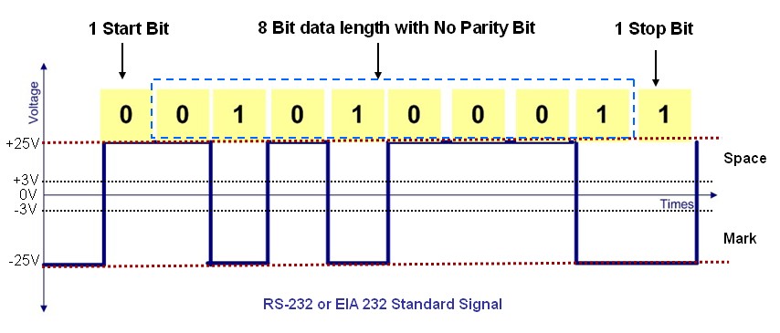
The RS-232 devices will transmit or receive the data in the serial form and use the voltage level to differentiate between the logical “0” called Space (+3 Volt to +25 Volt) and the logical “1” called Mark (-25 Volt to -3 Volt) as seen from this following RS-232 voltage’s graph:
The voltage level between -3 Volt to +3 Volt relative to the ground is considered undetermined condition. Every data transmitted or received has the format form of start bit, data bit, parity bit and stop bit; the mostly used configuration with the microcontroller is 1 start bit, 8 data bit with no parity bit and 1 stop bit. The transmission speed is measured in BAUD RATE; which equal to the number of bit per second for the RS-232 device to transmit and receive the data. For example the speed of 19000 baud means 19000 bits can be transmitted and received for every second.
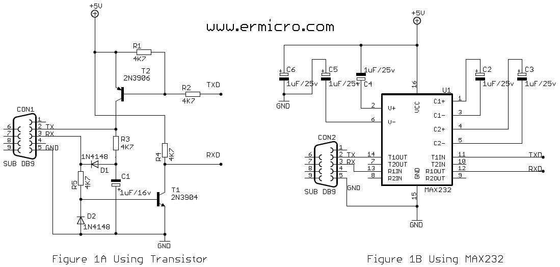
Because of the different voltage level between RS-232 and standard TTL/CMOS logic used in AVR microcontroller; therefore we use the voltage level shifter circuit to interface this two world. The following diagram is the commonly used circuit for this purpose; the first one use two transistors (Figure 1A) and the second one use the Dallas Semiconductor MAX-232 chip (Figure 1B):
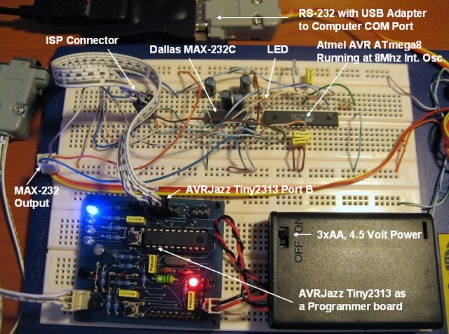
For the purpose of this project I will use this following hardware and software:
1. AVRJazz Tiny2313 board as the programmer board from ermicro
2. Atmel AVR ATmega8 for the target microcontroller
3. Dallas Semiconductor MAX-232 for the RS-232 voltage level shifter
4. WinAVR for the GNU’s C compiler
5. Atmel AVR Studio 4 for the coding, compiling and debugging environment
6. OspAvrII ver 5.47 Programmer from Mike Henning
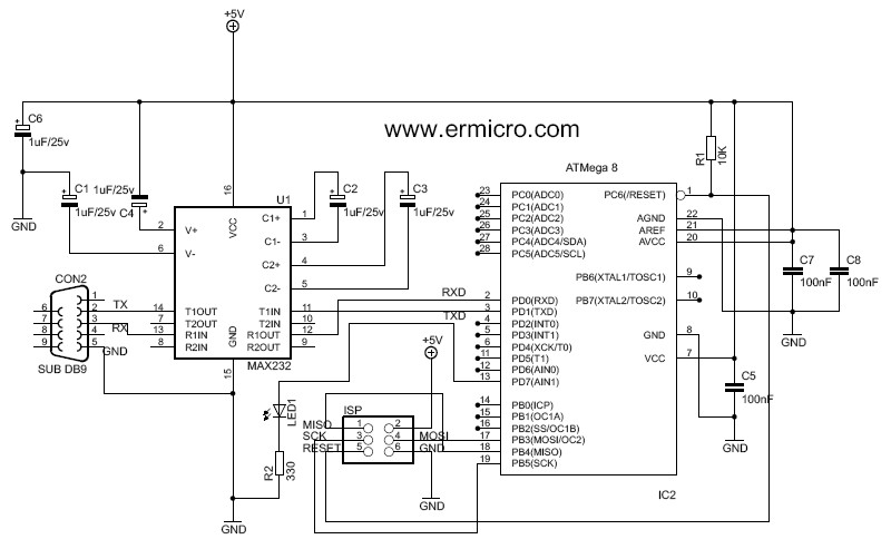
The complete schema for our project:
The C code for our example is a simple guessing game using the C’s rand() function to generate the random number to be guessed by the player. This game will use the window’s terminal emulation which connected to the computer COM port for demonstrating the Atmel AVR ATmega8 microcontroller UART (universal asynchronous receive and transmit) communication capabilities:
//************************************************************************
//  File Name	: Mega8Rs232.c
//  Version	: 1.0
//  Description : AVR ATMega8 UART
//  Author(s)	: RWB
//  Target(s)	: AVR ATmega8 Microcontroller
//  Compiler	: AVR-GCC 4.3.0; avr-libc 1.6.2 (WinAVR 20080610)
//  IDE         : Atmel AVR Studio 4.14
//  Programmer  : AVRJazz Tiny2313 board and AvrOspII
//************************************************************************
#include <avr/io.h>
#include <avr/interrupt.h>
#include <util/delay.h>
#include <stdio.h>
#include <stdlib.h>
#define BAUD_RATE   19200
#define MAX_GUESS   10
#define LEDPORT     PORTD
#define LED	    PD7
#define OVFTIMES    20
ISR(TIMER0_OVF_vect)
{
  static unsigned int iCount=1;
  iCount++;
  if (iCount >= OVFTIMES) {
    cli();
    LEDPORT |= (1<<LED);
    _delay_ms(50);
    LEDPORT &= ~(1<<LED);
    iCount=1;
    TCNT0=0;
    sei();
  }
}
void uart_init(void)
{
  UBRRH = (((F_CPU/BAUD_RATE)/16)-1)>>8;		// set baud rate
  UBRRL = (((F_CPU/BAUD_RATE)/16)-1);
  /* Enable Tx and Rx */
  UCSRB = (1<<RXEN)|(1<<TXEN);
  /* Set Frame: Data 8 Bit, No Parity and 1 Stop Bit */
  UCSRC = (1<<URSEL)|(1<<UCSZ1)|(1<<UCSZ0);
}
int uart_putch(char ch, FILE *stream)
{
   if (ch == '\n')
    uart_putch('\r', stream);
   while (!(UCSRA & (1<<UDRE)));
   UDR=ch;
   return 0;
}
int uart_getch(FILE *stream)
{
   unsigned char ch;
   while (!(UCSRA & (1<<RXC)));
   ch=UDR;

   /* Echo the output back to the terminal */
   uart_putch(ch,stream);

   return ch;
}
void ansi_cl(void)
{
  // ANSI clear screen: cl=\E[H\E[J
  putchar(27);
  putchar('[');
  putchar('H');
  putchar(27);
  putchar('[');
  putchar('J');
}
void ansi_me(void)
{
  // ANSI turn off all attribute: me=\E[0m
  putchar(27);
  putchar('[');
  putchar('0');
  putchar('m');
}
void ansi_cm(unsigned char row,unsigned char col)
{
  // ANSI cursor movement: cl=\E%row;%colH
  putchar(27);
  putchar('[');
  printf("%d",row);
  putchar(';');
  printf("%d",col);
  putchar('H');
}
int random_number(void)
{
   unsigned char num;

   num=(unsigned char) rand();
   return num % 99;
}
/* Assign I/O stream to UART */
FILE uart_str = FDEV_SETUP_STREAM(uart_putch, uart_getch, _FDEV_SETUP_RW);
int main(void)
{
  int i,secret,turn;
  /* Define Output/Input Stream */
  stdout = stdin = &uart_str;
  /* Initiatl UART */
  uart_init();
  /* Initial TIMER0 */
  TCCR0=(1<<CS02)|(1<<CS00);   // Use maximum prescale: Clk/1024
  TCNT0=0;                     // Start counter from 0
  TIMSK=(1<<TOIE0);            // Enable Counter Overflow Interrupt
  sei();                       // Enable Global Interrupt
  /* Initial Terminal */
  ansi_me();
  ansi_cl();                   // Clear Screen
  /* Initial Port D */
  DDRD = 0xFF;                 // Initial PORT D
  PORTD = 0;                   // Turn Off All PORT D
  /* Initial Variable Used */
  turn=MAX_GUESS;
  secret=random_number();
  for(;;) {
    if (turn == MAX_GUESS) {
      ansi_cl();
      secret=random_number();

      ansi_cm(1,12);
      printf("Welcome to Atmel AVR ATMega8 Microcontroller RS232 Project");
      ansi_cm(2,12);
      printf("----------------------------------------------------------");
      ansi_cm(4,1);
      printf("I have a secret number between 0 to 99\n");
      printf("You have %d times to guess my secret number!\n\n",turn);
    }
    printf("\n(%d) Enter your Number: ",turn);
    scanf("%d",&i);
    if (i > secret) {
      printf("\n\nYour number %d is higher then mine ! \n",i);
      turn--;
    }
    if (i < secret) {
      printf("\n\nYour number %d is lower than mine ! \n",i);
      turn--;
    }
    if (i == secret) {
      printf("\n\nCongratulation you found my secret number %d in %d times !\n",i,MAX_GUESS - turn);
      turn=MAX_GUESS;
      cli();
      _delay_ms(2000);
      sei();
    }
    if (turn <= 0) {
      printf("\n\nYou failed, my secret number is %d !\n",secret);
      turn=MAX_GUESS;
      cli();
      _delay_ms(2000);
      sei();
    }
  }
  return 0;	                  // Standard Return Code
}
On this project I will use ATMega8 Timer0 peripheral to blink the LED. The LED will be act as the program’s life beacon. Therefore as log as the LED is blinking we can assure that our program is working properly. Ok let’s move on to the project’s C code explanation:
A. The ATmega8 UART implementation
The UART implementation is consists of three functions:
- uart_init(): Initial the ATMega8 UART peripheral, this will set the RS-232 communication protocol such as Baud Rate, Data Length, Parity and Stop Bit
- uart_putch(): This routine will put the character directly into the UART port
- uart_getch(): This routine will read the character from the UART port
A.1. UART initiation
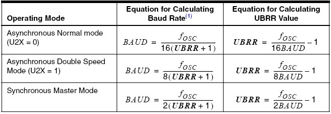
The initiation of UART peripheral in ATmega8 involving 4 registers, let’s take a look from the AVR ATmega8 datasheet on page 136 (you should have it near you right now); the first step we set the baud rate in the UBRRH register for the high order bits and in the UBRRL register for the low order bits according to this following formula:
For asynchronous normal operation mode at 19200 baud rate and using ATmeg8 internal frequency oscillator of 8 Mhz, the UBRR value will be:
UBRR = (8000000 / (16 * 19200)) – 1 = 25
The UBRR is the content of both UBRRH and UBRRL registers and must be integer from 0 to 4095. In order to get the high order bits from the formula result, we have to shift 8 times to the right before assign the value to UBRRH register, while for the low order bits; it will automatically cast or trimmed to the 8 bit in UBRRL register (see the datasheet on page 158).
UBRRH = (((F_CPU/BAUD_RATE)/16)-1)>>8;
UBRRL = (((F_CPU/BAUD_RATE)/16)-1);
Or you could simplified as
UBRRH = 0;
UBRRL = 25;
But using the first statements to assign the UBRR value to both UBRRH and UBRRL registers will be more practical because it will work in any frequency oscillator and baud rate we choose.
The next step is to enable both transmit and receive port which is PIN 2 and PIN 3 in ATmega8 by setting (asigned to logical 1) the bit RXEN and TXEN in the UCSRB register (see the datasheet on page 155):
UCSRB = (1<<RXEN)|(1<<TXEN);
Because we are not using the UART interrupt for both receive and transmit we just clear (assigned to logical 0) the RXC1E, TXC1E and UDRIE bits. The RXB8 and TXB8 is use for 9 bit data length so we also clear these two bits.
And the last one is to choose the RS-232 data frame for the asynchronous mode operation; 8 bit data length, no parity mode and 1 stop bit in the UCSRC register (see the datasheet on page 156):
UCSRC = (1<<URSEL)|(1<<UCSZ1)|(1<<UCSZ0);
With this statement we set the following RS232 data frame condition:
URSEL = 1 (for writing in UCSRC register)
UMSEL = 0 (select asynchronous mode operation)
UPM1  = 0 (select parity mode disable)
UMP2  = 0
USBS  = 0 (select 1 stop bit)
UCSZ2 = 0 (from UCSRB register; select 8 bit data length)
UCSZ1 = 1
UCSZ0 = 1
UCPOL = 0 (not use, it use for synchronous mode operation)
A.2. UART Transmitting Data function
Sending a data is simply putting the data into the USR register, but before assigning data to this register, we have to examine the UART data register empty (UDRE) flag status in the UCSRA register. This can be accomplished by using while statement to continuing loop as long as the UDRE bit status is “0“; and when the UART is ready for transmitting the UDRE bit will be set to “1” and the while loop statement will terminated.
while (!(UCSRA & (1<<UDRE)));
UDR=ch;
The first two statements inside this function is used to automatically append a line feed ASCII code (10) when we send the carriage return character (ASCII code 13).
if (ch == '\n')
    uart_putch('\r', stream);
A.2. UART Receiving Data function
Again the receiving data process is simply pooling the receive complete status (RXC) flag in the UCSRA register; when RXC bit is set (logical “1“); means the data is ready to be taken from the UDR register:
while (!(UCSRA & (1<<RXC)));
ch=UDR;
Any data received will be echoed back to terminal by sending the data back to the terminal using this following statement:
uart_putch(ch,stream);
B. The Terminal I/O Function:
To make our project implementation easier I use standard C I/O library (stdio.h) such as well known printf(), putchar() and scanf() functions for displaying output and reading input. Although using this library is heavy (the code is quit big), but… hey we are using AVR ATmega8 with 8 MB flash aren’t we? This mean we have plenty room for this library, so don’t worry just use it. In order for this C standard I/O function to work properly we have to tell the compiler to use our uart_getch() and uart_putch() as the basic I/O functions to be used by this library:
FILE uart_str = FDEV_SETUP_STREAM(uart_putch, uart_getch, _FDEV_SETUP_RW);
This statement will return the UART stream pointer to the uart_str variable, and by assigning the standard output and input stream to this pointer we connect all the I/O function to this stream as shown on this following statement inside the main() function:
stdout = stdin = &uart_str;
By using the standard C I/O, now it’s easy to display a formatted data such as this statement bellow:
printf("You have %d times to guess my secret number!\n\n",turn);
or reading formatted input such as this statement:
scanf("%d",&i);
C. The Terminal Emulator:
Our AVR ATmega8 will communicate with the computer through the RS-232 protocol. On the computer site we need to use the terminal emulation program that can communicate through the RS-232 protocol. On this project we just use the standard windows communication program called HyperTerminal; start the HyperTerminal program (Windows XP) by selecting start -> All Programs -> Accessories -> Communications -> HyperTerminal as follow:
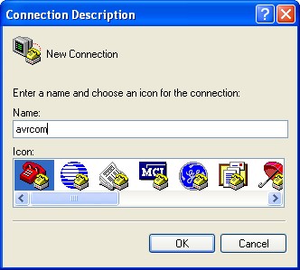
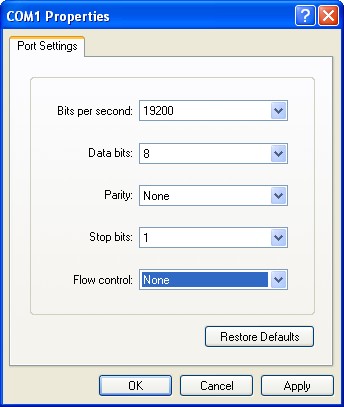
Name the connection as avrcom or whatever you like to call it; than click the Ok button, chose the communication port as follow (in this tutorial I use COM1 as it appear from USB to RS232 adapter driver):
Click the Ok button and set the communication data frame as follow:
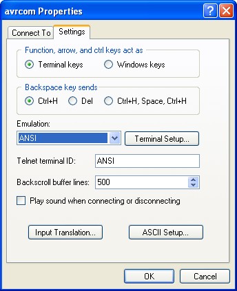
Click the Ok button and it will bring you to the terminal emulation screen; then set the properties of the terminal from menu File -> Properties and choose the Setting tab; select ANSI for the terminal emulation:
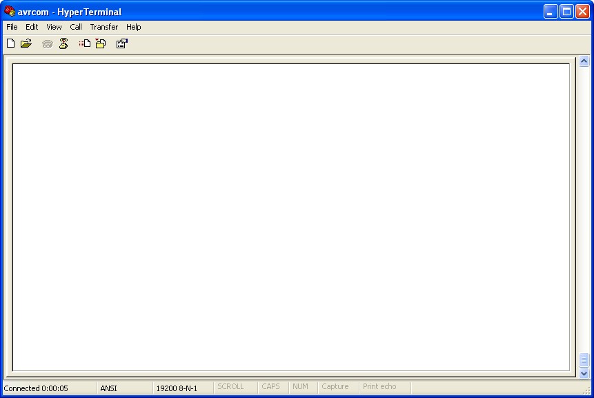
Now press the Ok button and it will bring you back to the blank white HyperTerminal’s screen as follow:
You could close and save the setting for this HyperTerminal profile (avrcom) for later use.
As I mention before; in the old days this kind of terminal is called a dumb terminal because it’s main function is just for inputting and displaying the data from and to the host computer (in this project the AVR ATmega8 microcontroller is act as the host computer); and since this is the most used method for communicating with the host computer at that time, many companies build their own brand an type of dumb terminals such as DEC vt100, vt220, vt320, WYSE 60, WYSE 50, etc; and to make it worse; every brand and type come with their own protocol or command for displaying character on screen such as clear the screen, moving the cursor, set the color attribute, the keyboard function key, etc.
Therefore in order for the host computer to communicate with wide varieties of terminal brand and type, the operating system have to keep all the terminal information in the table called /etc/termcap file in most UNIX like operating system and also could be found in the modern Linux distribution.
For the purpose of this tutorial, I just implement the ansi_cl(), ansi_cm() and ansi_me() functions which clear the screen, cursor movement and setting attribute off for the ANSI terminal emulation used in the HyperTerminal:
Clear Screen: cl=\E[H\E[J
Cursor Movement: cm=\E[%row;%colH
Set attribute off: me=\E[0m
The \E it’s the ESC character or ASCII code 27.
D. The AVR ATmega8 TIMER0:
The last is the TIMER0 implementation for the program’s life beacon. I am using the AVR ATmega8 interrupt service here to give an illusion of multi task program executing at the same time; this mean while your are playing with the microcontroller the LED connected to the PORTD-PD7 is also blinking.
To implement the TIMER0 peripheral in Atmel AVR Mega8 microcontroller; we simply set each of these three TCCR0, TCNT0 and TIMSK registers (see the datasheet on page 72):
TCCR0=(1<<CS02)|(1<<CS00);   // Use maximum prescaler: Clk/1024
TCNT0=0;                     // Start counter from 0
TIMSK=(1<<TOIE0);            // Enable Counter Overflow Interrupt
sei();                       // Enable the Global Interrupt
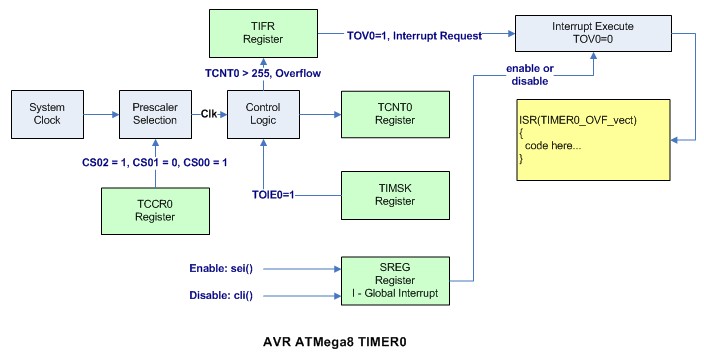
To activate the TIMER0 peripheral in the ATmega8 microcontroller, all we need is to enable the clock source for clocking the TCCR0 counter register, then the 8-bit counter register (TCNT0) will start to count from 0 up to 255 (top), when it count beyond 255 the TIFR register will send the interrupt request by setting the TOV0 bit (logical “1“). The microcontroller than will process the interrupt if TOIE0 bit in TIMSK register is set (logical “1“) and the global interrupt register flag I in SREG register is set (logical “1“). When the microcontroller execute the interrupt it will clear the TOV0 bit in TIFR register and the TCNT0 register will start to count from 0 (buttom) again; see the diagram bellow for the explanation of how this TIMER0 work:
When the microcontroller get the interrupt it will save the address of the next execute command to the stack (which is the SRAM) and start execute at the TIMER0 overflow interrupt address represented by ISR(TIMER0_OVF_vect) function in AVR C programming.
Inside the ISR function; we just wait for TCNT0 to overflow 20 times using the static variable iCount (you could experiment with the value define in OVFTIMES) before we blink the LED by toggling the PD7 (bit 7 on PORTD) on and off;
E. Bulding and Loading the Program:
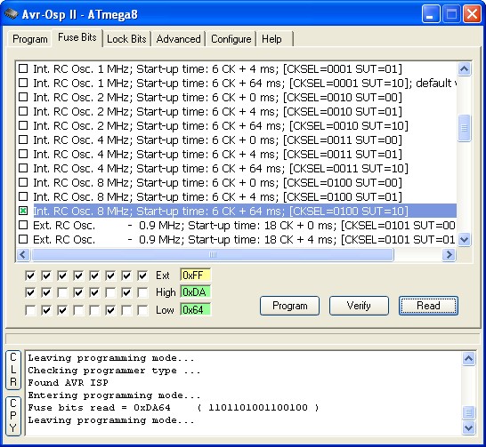
Before you build the program, you have to examine the AVR ATmega8 fuse bit, because we use the internal clock source, make sure you select the 8 Mhz internal RC oscillator. Connect the AVRJazz Tiny2313 board ISP programmer to the AVRMega8 ISP connector and start the AvrOspII programmer; change to the Fuse Bit tab and make sure you check the Int. RC Osc. 8 Mhz; Start-up time: 6 CK + 64 ms; [CKSEL=0100 SUT=10] option and leave the other setting to it’s default. Press Program button and press Read button to verify it.
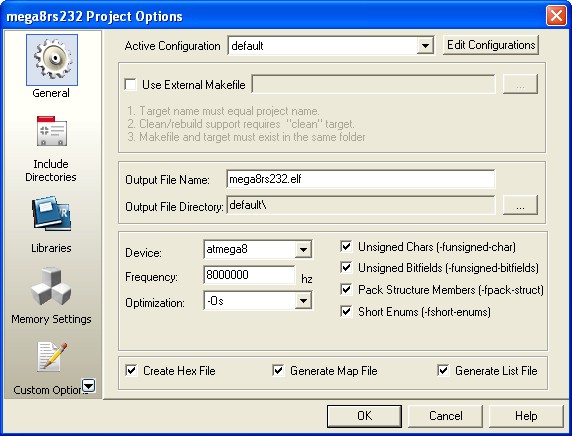
On the Atmel AVR Studio 4 choose the menu Project -> Configuration Option, fill the device frequency field box with 8000000 Hz as follow:
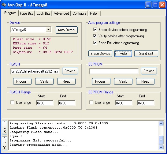
Press the Ok button, now you ready to compile the program using AVR Stuido 4 menu Build -> Rebuild All and download it to the AVR ATmega8 microcontroller using the AvrOspII program as follow:
Press the Auto button program to down load the code into the AVR ATmega8 microcontroller.
Activate your HyperTerminal program and now you are ready to play the guessing game with the AVR ATmega8, seeing how good you are to guess the number:
Bookmarks and Share


