Blog Entry
Build your own stopwatch using Maxim MAX7219 Serially Interfaced, 8-Digit LED Display Drivers
December 29, 2012 by rwb, under Microcontroller.
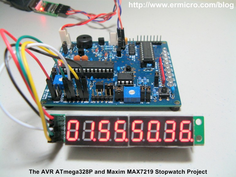
One of the basic usage of the TIMER peripheral on every microcontroller is to provide the accurate timing mechanism. Using the TIMER peripheral as the basic timing, we could easily develop a stopwatch and display it to the 8-Digit seven segment numeric LED display. Thanks to the Maxim MAX7219 chip which enable us to interface this 8-Digit seven segment LED display much easier using just three wires of the SPI (serial peripheral interface) to display the hour, minute, second, and hundredth of seconds to the 8-Digit seven segments LED display.
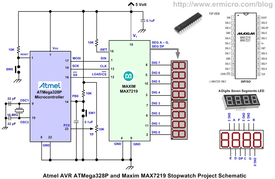
On this tutorial we will learn to utilize the Atmel AVR ATMega328P microcontroller SPI peripheral to communicate with the Maxim MAX7219 chip. The AVR ATmega328P SPI peripheral will be configured as a master and Maxim MAX7219 as the SPI device slave; you could read more about the SPI in Using Serial Peripheral Interface (SPI) Master and Slave with Atmel AVR Microcontroller project on this blog. A simplified electronic schematic of this project is shown in this following picture.
The following is the list of hardware, software, and references used to build this project:
1. One Maxim MAX7219: Serially Interfaced, 8-Digit LED Display Drivers
2. Two common cathode 4-Digits seven segment LED display
3. One Resistor: 10K Ohm
4. One Capacitors 0.1uF
5. AVRJazz 28PIN development board from ermicro which is based on the AVR ATmega328P microcontroller.
6. Atmel AVR Studio 6.0 for coding and debugging environment
7. STK500 programmer from AVR Studio 6.0, using the AVRJazz 28PIN board STK500 v2.0 bootloader
8. Atmel AVR ATmega328 and Maxim MAX7219 Datasheet
The stopwatch project that we are going to build has these following features:
- Stopwatch counting up to hundredth of second when the SW1 is pressed
- Pressing the SW1 once will freeze the counting display while continuing counting in the background, pressing the SW1 again will continue to display the stopwatch counting
- Adjust the intensity of the 8-Digits seven segment LED display using the trimmer potentiometer (TP).
- Reset the stopwatch counting by pressing the SW0.
In order to accomplish this project, we will use the AVR ATmega328P 16-bit TIMER2 peripheral in compare match mode as the heart beat of the counting mechanism, the pin change interrupt is used to detect the SW1 switch, and the ADC peripheral is used to adjust the 8-Digit seven segment LED display brightness. This project also serves as a good example of how we use many of the powerful AVR ATmega328P microcontroller features at the same time. The following is the complete C code for this project:
/*****************************************************************************
//  File Name    : SSegMAX7219.c
//  Version      : 1.0
//  Description  : Simple StopWatch Using Maxim MAX7219
//                 Serially Interfaced, 8-Digit LED Display Drivers
//  Author       : RWB
//  Target       : AVRJazz 28PIN Development Board
//  Compiler     : AVR-GCC 4.6.2 (AVR_8_bit_GNU_Toolchain_3.4.0_663)
//  IDE          : Atmel AVR Studio 6.0
//  Programmer   : AVRJazz 28PIN board STK500 v2.0 Bootloader
//               : AVR Visual Studio 6.0, STK500 programmer
//  Last Updated : 20 Dec 2012
*****************************************************************************/
#define F_CPU 16000000UL          // AVRJazz28PIN Board Used 16MHz
#include <avr/io.h>
#include <util/delay.h>
#include <avr/interrupt.h>

#define SPI_PORT PORTB
#define SPI_DDR  DDRB
#define SPI_CS   PB2

static volatile uint8_t hours,minutes,seconds,hdseconds;
static volatile uint8_t keystate;

void SPI_Write(uint8_t addr, uint8_t dataout)
{
  // Enable CS Pin
  SPI_PORT &= ~(1<<SPI_CS);

  // Start Address transmission (MOSI)
  SPDR = addr;

  // Wait for transmission complete
  while(!(SPSR & (1<<SPIF)));

  // Start Data transmission (MOSI)
  SPDR = dataout;

  // Wait for transmission complete
  while(!(SPSR & (1<<SPIF)));

  // Disable CS Pin
  SPI_PORT |= (1<<SPI_CS);
}

void disp_digit(uint8_t dindex,uint8_t number,uint8_t nmax) {
  uint8_t digit[2];

  if (keystate == 2) return;

  digit[0]=0;
  digit[1]=0;

  if (number <= nmax) {
    if (number < 10) {
     digit[0] = number;
    } else {
     digit[1] = number / 10;
     digit[0] = number - (digit[1] * 10);
    }
  }

  SPI_Write(dindex,digit[0] | 0x80); // Enable DP (Decimal Point)
  SPI_Write((dindex + 1),digit[1]);
}

ISR(TIMER1_COMPA_vect)
{
  // Increase the Hundred Seconds
  hdseconds++;            // Count-up Hundredth of Seconds
  disp_digit(1,hdseconds,99);
  if (hdseconds > 99) {
    hdseconds=0;
    seconds++;            // Count-up Seconds
    disp_digit(3,seconds,59);
    if (seconds > 59) {
      seconds=0;
      minutes++;          // Count-up Minutes
      disp_digit(5,minutes,59);
      if (minutes > 59) {
        minutes=0;
     hours++;          // Count-up Hours
     disp_digit(7,hours,23);
     if (hours > 23) hours=0;
      }
    }
  }
  TCNT1=0;                // Reset TIMER1 Counter
}

ISR(PCINT0_vect)
{
  if (PINB & (1<<PB0)) {       // Check PB0 if is Pressed or Logical 0
    if (keystate == 0) {
      TCNT1=0;
      TIMSK1=(1<<OCIE1A);      // Enable Compare A Interrupt
      keystate=1;
    } else {
    keystate++;
    if (keystate > 2) {
      keystate=1;
      disp_digit(1,hdseconds,99);
      disp_digit(3,seconds,59);
      disp_digit(5,minutes,59);
      disp_digit(7,hours,23);
    }
    }
  }
  PCIFR=(1<<PCIF0);                 // Clear Pin Change Interrupt Flag
}

uint8_t adc_map(uint8_t adc)
{
  return ((adc * 15) / 255);
}

int main(void)
{
  uint8_t cnt,ADCRead;

  // Set the PORTD as Output:
  DDRD=0xFF;
  PORTD=0x00;

  // Initial 16-bit TIMER1
  // TCNT1 Counter Increment Period: 1 / (Fclk/8)
  //                         Period = 1 / (16000000/8) = 0.0000005 Seconds
  // For 10 millisecond: 20,000 x 0.0000005 = 0.01 Seconds
  TCCR1A=0;                         // Normal Mode
  TCCR1B=(1<<CS11);                 // Use prescaler of 8
  TCNT1=0;                          // Start TIMER1 counter from 0

  OCR1A=20000;                      // The Hundredth Second
  TIFR1=(1<<OCF1A);                 // Clear any pending Compare A Interrupt
  TIMSK1=0;                         // Disable Compare A Interrupt

  // Initial ATmega328P Pin Change Interrupt on PB0 (PCINT0)
  PCMSK0 |= (1<<PCINT0);              // Activate PCINT0 Pin Change Interrupt
  PCICR |= (1<<PCIE0);                 // Enable PCIE0 Pin Change Interrupt
  keystate=0;                       // Key State

  // Set ADCSRA Register on ATmega328P
  // ADEN=1 - Enable the ADC Peripheral
  // ADPS2=1, ADPS1=1, and ADPS0=1 we used prescale of 128
  ADCSRA = (1<<ADEN) | (1<<ADPS2) | (1<<ADPS1) | (1<<ADPS0);
  ADCSRB = 0b00000000;          // Free Running Mode
  DIDR0  = 0b00000000;          // Use analog input for Channel 0 to 5

  // Set ADMUX Register on ATmega328P
  // Use External Voltage Reference, Left Adjust, and select the ADC channel 0
  ADMUX=0b01100000;

  // Initial the AVR ATMega328P SPI Peripheral
  // Set MOSI and SCK as output, others as input
  SPI_DDR = (1<<PB3)|(1<<PB5)|(1<<PB2);

  // Disable (RCK Low)
  SPI_PORT |= (1<<SPI_CS);

  // Enable SPI, Master, set clock rate fck/2 (maximum)
  SPCR = (1<<SPE)|(1<<MSTR);
  SPSR = (1<<SPI2X);

  // Set the MAX7219
  SPI_Write(0x0C,0x01);        // Normal Operation
  SPI_Write(0x09,0xFF);        // Code B Decode for Digit 7 to 0
  SPI_Write(0x0B,0x07);        // Scan digit 7 to 0
  SPI_Write(0x0A,0x0F);        // Set Default Intensity to Max

  // Reset all Digit and set the Decimal Point
  for(cnt=1;cnt <= 8;cnt=cnt+2) {
    SPI_Write(cnt,0 | 0x80);
    SPI_Write(cnt + 1,0);
  }

  sei();                           // Enable Global Interrupt

  for(;;) {
   // Start ADC conversion by setting ADSC on ADCSRA Register
   ADCSRA |= (1<<ADSC);

   // wait until conversion complete ADSC=0 -> Complete
   while (ADCSRA & (1<<ADSC));

   // Get the 8-bit ADC the Result
   ADCRead=ADCH;

   // Set the MAX7219 Intensity
   SPI_Write(0x0A,adc_map(ADCRead));

   // Put Some Delay Here
   _delay_ms(100);
  }
  return 0;
}

/* EOF: SSegMAX7219.c */
The Maxim MAX7219
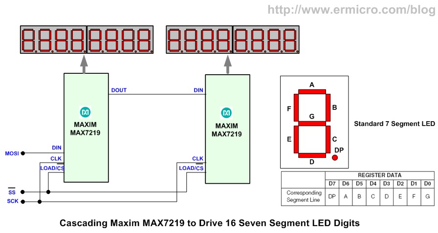
The MAX7219 chip from maxim is a powerful serial input/output common-cathode display driver that interfaces microcontroller to 7-segment numeric LED displays of up to 8 digits. It has a build-in BCD (binary code decimal) decoder and a brightness control. Although the main function is to drive the 8-Digits seven segment LED display but because it also capable to drive an individual LED segment i.e. segment A to segment G and DP (decimal point), therefore you could also use this chip to drive the individual LED, the LED bar-graph, or the 8×8 LED matrix display. The MAX7219 could easily be daisy-chained (cascaded) to another MAX7219 chip using the DOUT pin which is useful when you want to drive 16-Digits LED display or several LED matrix display.
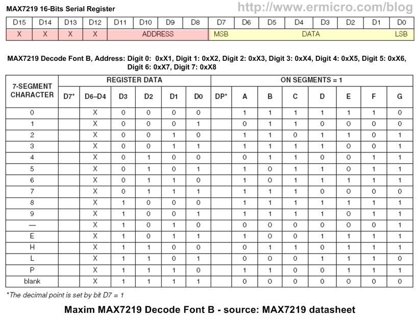
The MAX7219 chip has 16-bit registers divided into two sections; the first upper byte (bit 8 to 15) is called the address and the lower byte (bit 0 to 7) is called the data.
In order to send a command to the MAX7219 chip, first we need send the 8-bits address and next we send the 8-bits data. For example if we want to display a character 6 (six) on digit 0, then first we send the address 0x01 to select the digit 0 and next we send the value 0x06 to the MAX7219 16-bits register.
The same principle is also apply to other important MAX7219 chip commands such as activate from the shutdown mode (normal operation), use BCD decode (font B) mode, scanning limit (scanning digit 0 to 7), and adjusting the seven segment LED digit intensity please refer to the Maxim MAX7219 datasheet for the complete explanation.
The AVR ATmega328P TIMER1 Peripheral
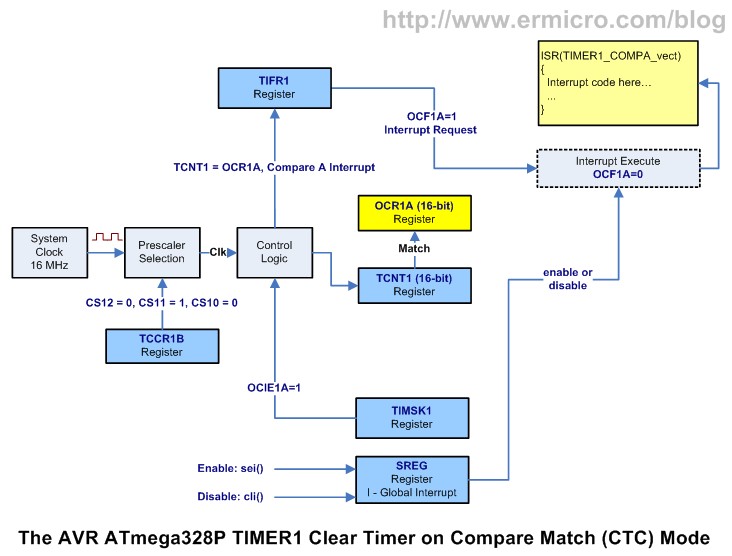
The 16-bits TIMER1 peripheral is the heart beat of this stopwatch project. We used this 16-bit TIMER1 as it give more flexibility to implement the stopwatch, because of the 16-bit counter length, therefore it could counting up to 65.536 before overflow. We will use TIMER1 16-bit output compare register OCR1A (OCR1AH – OCR1AL) as the base of our hundredth of seconds counter.
The Output Compare Register A (OCR1A) will be the maximum value of TCNT1 register counter before it generate an interrupt. Using the AVRJazz 28PIN development board 16 Mhz external crystal resonator with prescaler of 8, we could calculate the TIMER1 clock period as follow:
TIMER1 Clock Period = 1 / (16000000 / 8) = 0.0000005 seconds
To get a hundredth of seconds period, the TIMER1 digital counter TCNT1 register will need to count up to value of 20,000:
The hundredth of seconds = 20000 x 0.0000005 seconds = 0.01 seconds.
By assigning this value to the OCR1A register and activate the output compare register A interrupt, the compare match interrupt will be generated every 0.01 seconds. The following C code is the setup for the AVR ATmega328P TIMER1:
// Initial 16-bit TIMER1
// TCNT1 Counter Increment Period: 1 / (Fclk/8)
// Period = 1 / (16000000/8) = 0.0000005 Seconds
// For 10 millisecond: 20,000 x 0.0000005 = 0.01 Seconds
TCCR1A=0; // Normal Mode
TCCR1B=(1<<CS11); // Use prescaler of 8
TCNT1=0; // Start TIMER1 counter from 0
OCR1A=20000; // The Hundredth Second

TIFR1=(1<<OCF1A); // Clear any pending Compare A Interrupt
TIMSK1=0; // Disable Compare A Interrupt
Next inside the compare match interrupt routine we count-up the variable hdseconds, seconds, minutes, and hours as shown on this following C code:
ISR(TIMER1_COMPA_vect)
{
  // Increase the Hundred Seconds
  hdseconds++;            // Count-up Hundredth of Seconds
  disp_digit(1,hdseconds,99);
  if (hdseconds > 99) {
    hdseconds=0;
    seconds++;            // Count-up Seconds
    disp_digit(3,seconds,59);
    if (seconds > 59) {
      seconds=0;
      minutes++;          // Count-up Minutes
      disp_digit(5,minutes,59);
      if (minutes > 59) {
        minutes=0;
     hours++;          // Count-up Hours
     disp_digit(7,hours,23);
     if (hours > 23) hours=0;
      }
    }
  }
  TCNT1=0;                // Reset TIMER1 Counter
}
Noticed inside this interrupt routine we also run the disp_digit() function which is used to send the command to the MAX7219 chip to display the corresponding digit but in order to reduce the overall execution time inside the interrupt routine we only display the changed digit at the time.
The AVR ATmega328P External Interrupt
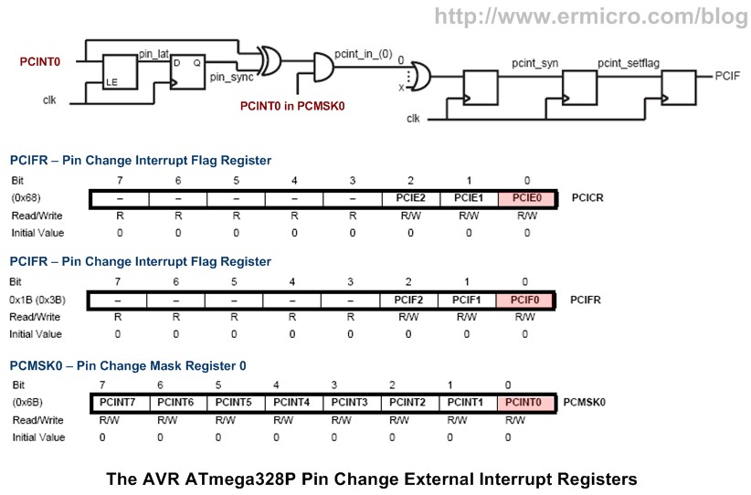
The ATmega328P support two type of an external interrupt, this first one are triggered by INT0 (PD2) and INT1 (PD3) input pins and the second one are triggered by pin change on any of PCINT0, PCINT1, PCINT2, to PCINT23 input pins. The INT0 and INT1 could generate an interrupt on four input signal type i.e. “Low Logical Level”, “Any Logical Change”, “Falling Edge”, and “Rising Edge” input signal, while the pins change interrupt pins only capable to generate an interrupt on “Any Logical Change” as shown in this following table:
Both of these interrupt type has a common used, which is to generate an interrupt based on any signal change on the particular I/O ports. The external interrupt request has more flexible digital input type event but limited only on two I/O ports PD2 and PD3, while the pin change interrupt request has only one type event i.e. logical change, but it could be applied to all the ATmega328P microcontroller I/O ports.
In this project, we will use the AVRJazz 28PIN user switch SW1 (connected to PB0 pin) to generate the external interrupt (i.e. PCINT0) to control the stopwatch. The C code to initialize the AVR ATmega328P pin change interrupt is shown on these following lines:
// Initial ATmega328P Pin Change Interrupt on PB0 (PCINT0)
PCMSK0 |= (1<<PCINT0); // Activate PCINT0 Pin Change Interrupt
PCICR |= (1<<PCIE0); // Enable PCIE0 Pin Change Interrupt
By setting the PCINT0 bit in pin change interrupt mask 0 register (PCMSK0) we activate the PB0 I/O port as the pin change interrupt source. Next we enable the PCIE0 bit in pin change interrupt control register (PCICR) and global interrupt to enable the interrupt.
When the pin change interrupt occur the program will jump to the interrupt address (PCINT0_vector) and execute the C code inside this function:
ISR(PCINT0_vect)
{
  if (PINB & (1<<PB0)) {       // Check PB0 if is Pressed or Logical 0
    if (keystate == 0) {
      TCNT1=0;
      TIMSK1=(1<<OCIE1A);      // Enable Compare A Interrupt
      keystate=1;
    } else {
    keystate++;
    if (keystate > 2) {
      keystate=1;
      disp_digit(1,hdseconds,99);
      disp_digit(3,seconds,59);
      disp_digit(5,minutes,59);
      disp_digit(7,hours,23);
    }
    }
  }
  PCIFR=(1<<PCIF0);                 // Clear Pin Change Interrupt Flag
}
When the pin change interrupt occur on PB0 we simply assign and examine the keystate variable. After system reset (pressing SW0), pressing the SW1 will activate the TIMER1 output compare match A interrupt. Next when we press the SW1 i.e. keystate variable is equal to 2, the disp_digit() function will simply return to the caller function( i.e. the TIMER1 compare match A interrupt) without sending any new display information to the MAX7219 chip. This allows the stopwatch counter to keep count while freezing the 8-Digits seven segment LED display.
Inside the Project C code
The C code begin with initializing all the necessary ATmega328P microcontroller peripheral such as the TIMER1 peripheral, external interrupt peripheral, SPI peripheral, and the Analog to Digital Conversion (ADC) peripheral where we just use the 8-bit resolution (left adjust) as the MAX7219 intensity level is only have 16 steps i.e. 0 to 15, therefore we don’t need to use the 10-bits resolution of the ATmega328P ADC peripheral. For more information about using the ATmega328P microcontroller ADC you could read Analog to Digital Converter AVR C Programming articles on this blog.
Next we configure the MAX7219 chip using SPI_Write() function where we activate the MAX7219 chip in normal operation, use the decode mode, activate digit scanning for digit 0 to 7, and set the default intensity to maximum as shown in this following C code:
// Set the MAX7219
SPI_Write(0x0C,0x01);        // Normal Operation
SPI_Write(0x09,0xFF);        // Code B Decode for Digit 7 to 0
SPI_Write(0x0B,0x07);        // Scan digit 7 to 0
SPI_Write(0x0A,0x0F);        // Set Default Intensity to Max

// Reset all Digit and set the Decimal Point
for(cnt=1;cnt <= 8;cnt=cnt+2) {
  SPI_Write(cnt,0 | 0x80);
  SPI_Write(cnt + 1,0);
}
After activating global interrupt sei() function, the program entering the infinite loop. Inside the infinite loop we read the trimmer potentiometer (TP) value and map this value (i.e. 0 to 255) to the MAX7219 chip intensity setting value (i.e. 0 to 15) using the adc_map() function before sending the command to the MAX7219 chip. Now you could enjoy the following video that showing this stopwatch project in action:
The Final Though
The Maxim MAX7219 chip has much more possible interesting application especially when we used it as the individual LED driver, take advantage of its cascading ability we could even drive large number of LEDs (e.g. RGB LEDs). For example if you cascade two MAX7219 chips, in order to send information to the second MAX7219 chip you need to send two 16-bit values, the first 16-bit value will be for the second MAX7219 chip and the last 16-bit value should be the no operation command i.e. address: 0x00 and data: 0x00 for the first MAX7219 chip. The same principle also applies if you want to cascade several MAX7219 chips, Ok I leave this challenge for your experiment’s pleasure
Bookmarks and Share




Comment by klyx.
Nice to see your new article Mr. Besinga. MAX7219/MAX7221 are great IC from Maxim but unfortunately the price too high, $10 on low quantities. AS1106/AS1107 from Austria Microsystems are alternative version and full compatible (drop in replacement) with Maxim counterparts, the price are roughly half on low quantities