Blog Entry
Developing Embedded Application with BASIC Language on the Microchip PIC18F Microcontroller using the Amicus18 Development system
December 24, 2011 by rwb, under Microcontroller.
The BASIC (Beginners’ All-purpose Symbolic Instruction Code) language has been known as one of the popular high level language choice in embedded system today. In fact the born and development of the personal computer (PC) we use today has been influenced by the used of BASIC language. Today there are many of professional BASIC language development tools variant targeting the Microchip PIC microcontroller.
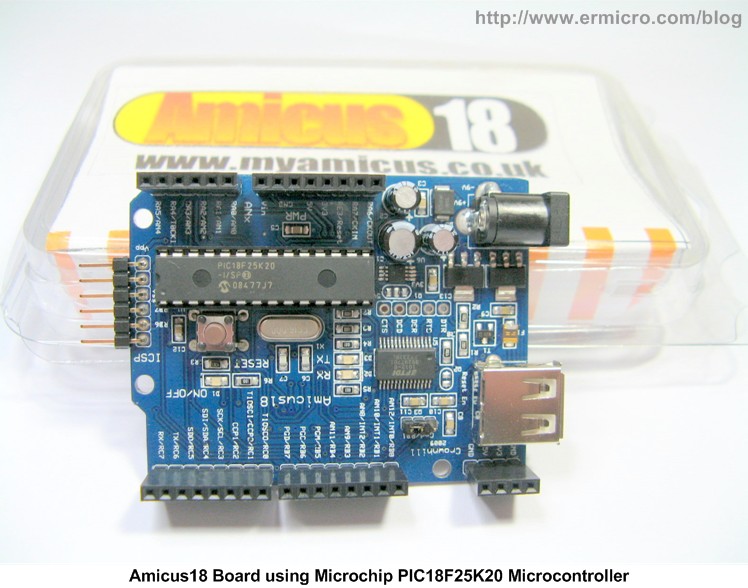
On this project we will focus on the Amicus18 Proton BASIC for Microchip PIC compiler and the Amicus18 development board from Crownhill Associates and learn of how to use the Amicus18 development environment to interface with the Philips PCA8574 I2C I/O Expander connected to 2×16 Hitachi HDU44780U (or its compatible) LCD.
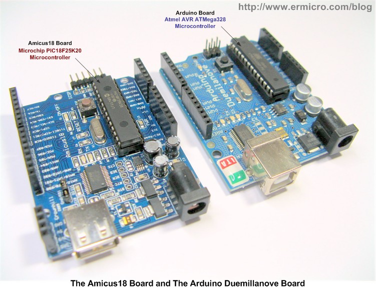
Inspired by the popular Arduino open source development system the Amicus18 board is designed to make used of various Arduino hardware add on modules or known as the Arduino shield which is widely available on the market, therefore the Amicus18 board use the same Arduino board form factor as well as the Arduino I/O port sockets as shown on this following picture:
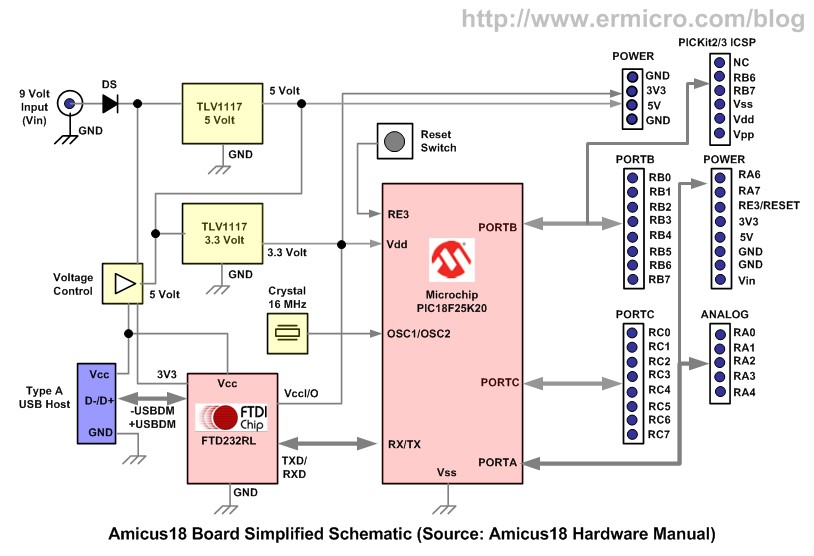
Unlike the Arduino board which is based on the Atmel 8-bits AVR ATMega328 microcontroller, the Amicus18 board is based on the Microchip 8-bits PIC18F25K20 microcontroller, therefore you could not use the Arduino development environment on the Amicus18 board. The other things that make this two board differ is the Amicus18 board use the PIC18F25K20 microcontroller which is based on the 3.3 volt working voltage while the Arduino board ATMega328 microcontroller used the 5 volt working voltage. Because of the working voltage different, make interfacing the Amicus18 board with many of the available Arduino shield board has to be examined carefully in order to make it work correctly.
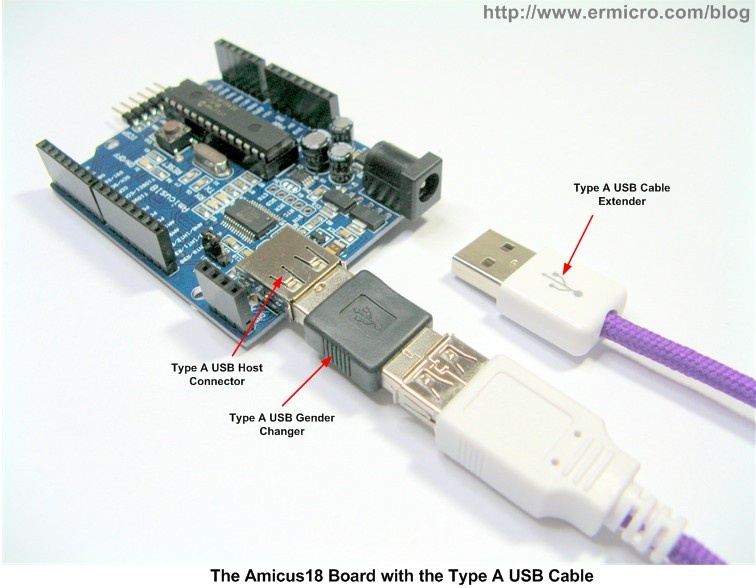
One thing that bothers me when first using the Amicus18 board is the type A USB host connector used by the Amicus18 board similar to the type A USB host connector used in many PC (personal computer), because we have to connect the Amicus18 board with the computer in order to program it, therefore we have to use the USB cable that has similar type A USB plug on both ends (Arduino use type B USB host connector). This uncommon type of the USB cable and is quite hard to find in the market, so in this project I used the type A USB gender changer and type A USB cable extender as shown on this following picture:
The Amicus18 Development Environment
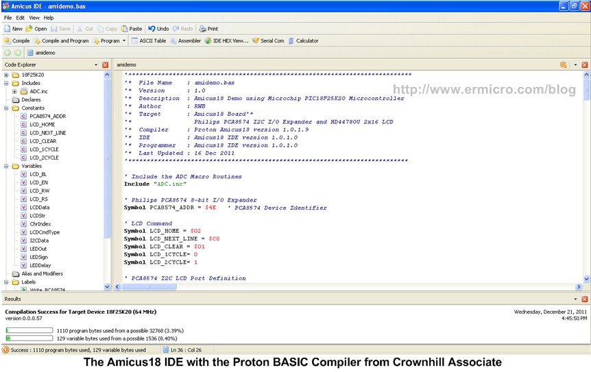
The Amicus18 development environment is equipped with a free professional grade Proton BASIC compiler which is specially configured to be used with the Amicus18 board or to be more specific, this special edition of Proton BASIC compiler could only be used with the Microchip PIC18F25K20 microcontroller without any restriction and its fully optimized.
Later on after hearing the request from many of the Amicus18 users, start on version 1.0.1.6 of the Proton Amicus18 Compiler (June 2011), they added support to the Microchip PIC18F25K22 microcontroller (5 volt version) as well as the original Amicus18 board Microchip PIC18F25K20 microcontroller (3.3 volt version) through the device directive Device = 18F25K20 or Device = 18F25K22 statement. Without the device directive statement the Amicus18 proton BASIC compiler will automatically use 18F25K20
But if you want to program the Amicus18 using the Microchip PIC18F25K22 (5 volt version) you have to use the Microchip PICKit2 or PICKit3 programmer because currently the Amicus18 board only support the Microchip PIC18F25K20 microcontroller (3.3 volt version) bootloader. Of course if you want to use the Amicus18 Proton BASIC for other type of Microchip PIC microcontroller you have to buy a full license of the Proton BASIC Compiler.
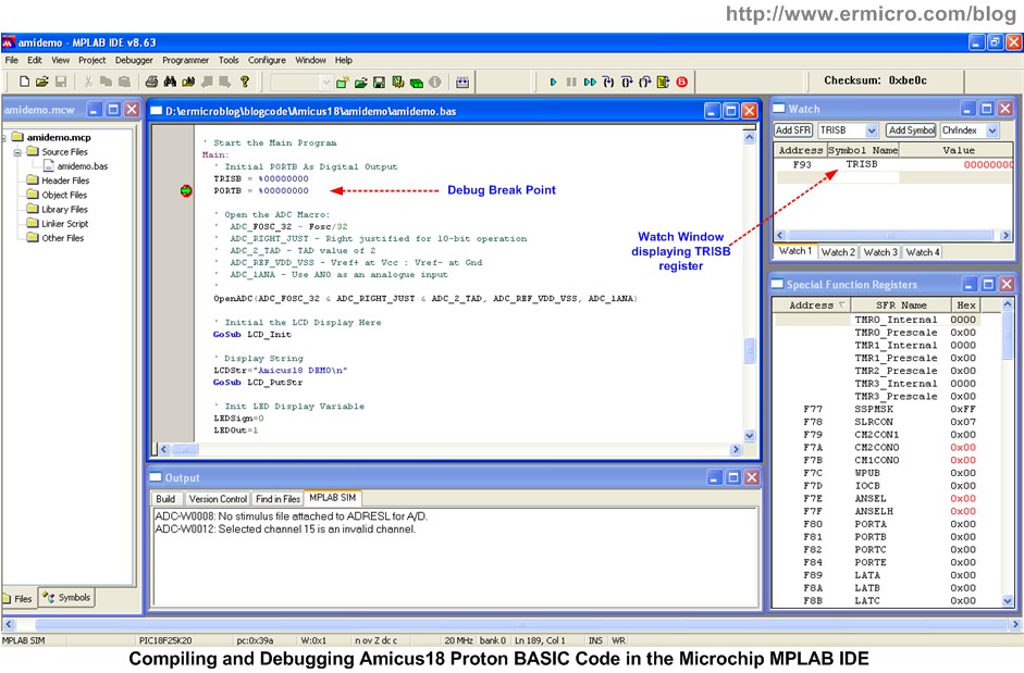
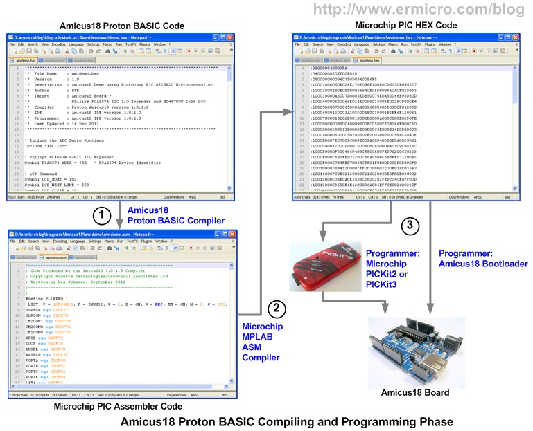
The Amicus18 proton BASIC compiler use the Microchip MPLAB ASM to generate the HEX code required by the Microchip PIC18F25K20 microcontroller, therefore you could easily compile and debug the Proton BASIC code using the Microchip MPLAB IDE as shown on this following picture:
For more information on how to integrate the Amicus18 Proton BASIC compiler with the Microchip MPLAB IDE please read the “Using Amicus18 Compiler with The MPLAB IDE” documentation which come with the Amicus18 IDE.
The Amicus18 Board I2C LCD Project
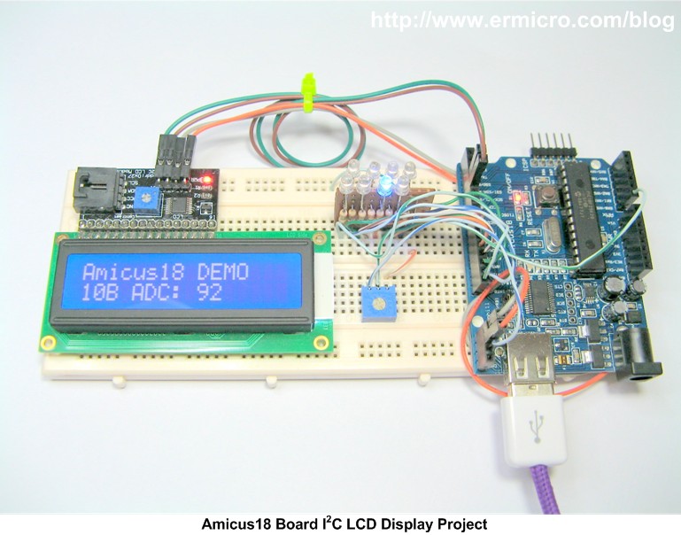
As I mention before in this project we will learn to interface the Amicus18 board to the Philips PCA8574 I2C I/O Expander connected to 2×16 HDU44780U LCD and at the same time you could learn of how to use the Proton BASIC language to handle Microchip PIC18FK25K20 MSSP (Master Synchronous Serial Port) in I2C (read as I square C) mode and the ADC (Analog to Digital Converter) peripheral.
Now let’s list down all the necessary hardware, software, and some supported documents in order to accomplish this project objective:
- The Amicus18 Board which you could be purchased from Farnell
- PCA8574 Philips/NXP 8-bit I/O expander for I2C-bus
- One Hitachi HD44780U or compatible 2×16 LCD with blue back light
- SMD Resistors 1K (1), 4.7K (1), and 10K (2)
- 8 Resistors 330 Ohm (0.25 watt)
- Two 10K Trimpot
- One SMD LED (1)
- Blue LED (3 mm)
- One SMD N-Channel MOSFET MMBF170 or equivalent
- Breadboard and breadboard jumper cables
- Microchip MPLAB IDE version 8.63 or the latest
- Amicus18 IDE and Proton BASIC Compiler from Crownhill Associates
- Reference Document: Microchip PIC18F25K20 datasheet, Philips/NXP PCA8574 datasheet, Amicus18 Hardware Manual, and Proton Amicus18 Compiler.
The following is the complete Amicus18 Proton BASIC code for this project:
'*****************************************************************************
'*  File Name    : amidemo.bas
'*  Version      : 1.0
'*  Description  : Amicus18 Demo using Microchip PIC18F25K20 Microcontroller
'*  Author       : RWB
'*  Target       : Amicus18 Board
'*                 Philips PCA8574 I2C I/O Expander and HD4478OU 2x16 LCD
'*  Compiler     : Proton Amicus18 version 1.0.1.9
'*  IDE          : Amicus18 IDE version 1.0.1.0
'*  Programmer   : Amicus18 IDE version 1.0.1.0
'*  Last Updated : 16 Dec 2011
'****************************************************************************

' Include the ADC Macro Routines
Include "ADC.inc"

' Philips PCA8574 8-bit I/O Expander
Symbol PCA8574_ADDR = $4E   ' PCA8574 Device Identifier

' LCD Command
Symbol LCD_HOME = $02
Symbol LCD_NEXT_LINE = $C0
Symbol LCD_CLEAR = $01
Symbol LCD_1CYCLE= 0
Symbol LCD_2CYCLE= 1

' PCA8574 I2C LCD Port Definition
' P7,P6,P5,P4 = Data, P3=Backlight (BL), P2=E, P1=RW, P0=RS
Dim LCD_BL As Byte
Dim LCD_EN As Byte
Dim LCD_RW As Byte
Dim LCD_RS As Byte

' Define Variables Used in I2C LCD Routine
Dim LCDData As Byte
Dim LCDStr As String * 20
Dim ChrIndex As Byte
Dim LCDCmdType As Byte
Dim I2CData As Byte

Dim LEDOut As Byte
Dim LEDSign As Byte
Dim LEDDelay As Word

' Initial the LCD Variables Used
LCD_BL=%00001000
LCD_EN=%00000100
LCD_RW=%00000010
LCD_RS=%00000001

' Goto Main Program Here
GoTo Main

Write_PCA8574:
  HBStart              ' Send a Start condition
  HBusOut PCA8574_ADDR ' Send a WRITE command to PCA8574
  HBusOut I2CData      ' Send Data to PCA8574
  HBusNack             ' Send No Acknowledge to PCA8574
  HBStop               ' Send a Stop condition
  DelayUS 100          ' Put the 100us Delay Here

  Return
' EOF: Write_PC8574 Subroutine

LCD_PutCmd:
  ' Put the Upper 4 bits data
  I2CData = (LCDData & $F0)|LCD_BL|LCD_EN
  GoSub Write_PCA8574
  DelayUS 20

  ' Write Enable Pulse E: Hi -> Lo
  I2CData = I2CData & ~LCD_EN
  GoSub Write_PCA8574
  DelayUS 5

  If LCDCmdType = 1 Then
    ' Put the Lower 4 bits data
    I2CData = ((LCDData << 4) & $F0)|LCD_BL|LCD_EN
    GoSub Write_PCA8574
    DelayUS 20

    ' Write Enable Pulse E: Hi -> Lo
    I2CData = I2CData & ~LCD_EN
    GoSub Write_PCA8574
    DelayUS 5
  EndIf
  Return
' EOF LCD_putmcd Subroutine

LCD_PutCh:
  ' Put the Upper 4 bits data
  I2CData = (LCDData & $F0)|LCD_BL|LCD_EN|LCD_RS
  GoSub Write_PCA8574
  DelayUS 20

  ' Write Enable Pulse E: Hi -> Lo
  I2CData = I2CData & ~LCD_EN
  GoSub Write_PCA8574
  DelayUS 5

  ' Put the Lower 4 bits data
  I2CData = ((LCDData << 4) & $F0)|LCD_BL|LCD_EN|LCD_RS
  GoSub Write_PCA8574
  DelayUS 20

  ' Write Enable Pulse E: Hi -> Lo
  I2CData = I2CData & ~LCD_EN
  GoSub Write_PCA8574
  DelayUS 5
  Return
' EOF LCD_putch Subroutine

LCD_Init:
  DelayMS 30

  ' Send Command $30
  LCDData=$30
  LCDCmdType=LCD_1CYCLE
  GoSub LCD_PutCmd

  ' Wait for more than 4.1 ms
  DelayMS 8

  ' Send Command $30
  LCDData=$30
  LCDCmdType=LCD_1CYCLE
  GoSub LCD_PutCmd

  ' Wait for more than 100 us
  DelayMS 1

  ' Send Command $30
  LCDData=$30
  LCDCmdType=LCD_1CYCLE
  GoSub LCD_PutCmd

  ' Function set: Set interface to be 4 bits long (only 1 cycle write).
  LCDData=$20
  LCDCmdType=LCD_1CYCLE
  GoSub LCD_PutCmd

  ' Function set: DL=0;Interface is 4 bits, N=1; 2 Lines, F=0; 5x8 dots font)
  LCDData=$28
  LCDCmdType=LCD_2CYCLE
  GoSub LCD_PutCmd

  ' Display Off: D=0; Display off, C=0; Cursor Off, B=0; Blinking Off
  LCDData=$08
  LCDCmdType=LCD_2CYCLE
  GoSub LCD_PutCmd

  ' Display Clear
  LCDData=LCD_CLEAR
  LCDCmdType=LCD_2CYCLE
  GoSub LCD_PutCmd

  ' Entry Mode Set: I/D=1; Increment, S=0; No shift
  LCDData=0x06
  LCDCmdType=LCD_2CYCLE
  GoSub LCD_PutCmd

  ' Display On, Cursor Off
  LCDData=0x0C
  LCDCmdType=LCD_2CYCLE
  GoSub LCD_PutCmd
  Return
' EOF LCD_Init Subroutine

LCD_PutStr:
  ChrIndex = 0                ' Start at position 0 within the string
  Repeat
    LCDData=LCDStr[ChrIndex]
    If LCDData = $0A Then
      LCDData=LCD_NEXT_LINE
      LCDCmdType=LCD_2CYCLE
      GoSub LCD_PutCmd
    Else
      GoSub LCD_PutCh
    EndIf
    Inc ChrIndex              ' Move to next position within string
  Until ChrIndex = Len LCDStr
  Return
' EOF LCD_PutStr Subroutine

' Start the Main Program
Main:
  ' Initial PORTB As Digital Output
  TRISB = %00000000
  PORTB = %00000000

  ' Open the ADC Macro:
  '  ADC_FOSC_32 - Fosc/32
  '  ADC_RIGHT_JUST - Right justified for 10-bit operation
  '  ADC_2_TAD - TAD value of 2
  '  ADC_REF_VDD_VSS - Vref+ at Vcc : Vref- at Gnd
  '  ADC_1ANA - Use AN0 as an analogue input
  '
  OpenADC(ADC_FOSC_32 & ADC_RIGHT_JUST & ADC_2_TAD, ADC_REF_VDD_VSS, ADC_1ANA)

  ' Initial the LCD Display Here
  GoSub LCD_Init

  ' Display String
  LCDStr="Amicus18 DEMO\n"
  GoSub LCD_PutStr

  ' Init LED Display Variable
  LEDSign=0
  LEDOut=1

  While 1 = 1                ' Create an endless loop
    ' Reading the 10K Trimpot on AN0
    LEDDelay= ADIn 0

    ' Display on LCD
    LCDData=LCD_HOME
    LCDCmdType=LCD_2CYCLE
    GoSub LCD_PutCmd

    LCDData=LCD_NEXT_LINE
    LCDCmdType=LCD_2CYCLE
    GoSub LCD_PutCmd

    LCDStr="10B ADC: " + Str$(Dec LEDDelay) + "  "
    GoSub LCD_PutStr

    If LEDSign = 0 Then
      PORTB=LEDOut
      DelayMS LEDDelay
      LEDOut=LEDOut << 1
      If LEDOut >= $80 Then
        LEDSign=1
      EndIf
    Else
      PORTB=LEDOut
      DelayMS LEDDelay
      LEDOut=LEDOut >> 1
      If LEDOut <= $01 Then
        LEDSign=0
      EndIf
    EndIf
  Wend
' EOF: amidemo.bas
The I2C LCD Display
The I2C (read as I square C) bus has been introduced in 1980 by Philips, and has become a de-facto world standard for data exchange between Microcontroller and various devices. The advantage of using the I2C device is because it only requires 2 wires in order to communicate to the I2C device and you could attach many of the I2C devices simultaneously on the same I2C bus. You could read more information about how the I2C protocol works in the Interfacing the Microchip PIC18 Microcontroller Master Synchronous Serial Port (MSSP) to various I2C Devices article.
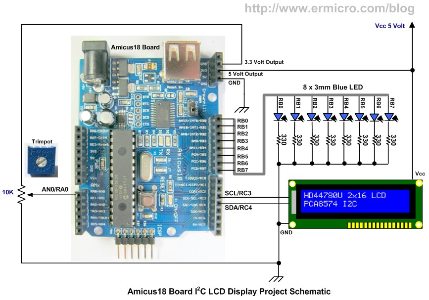
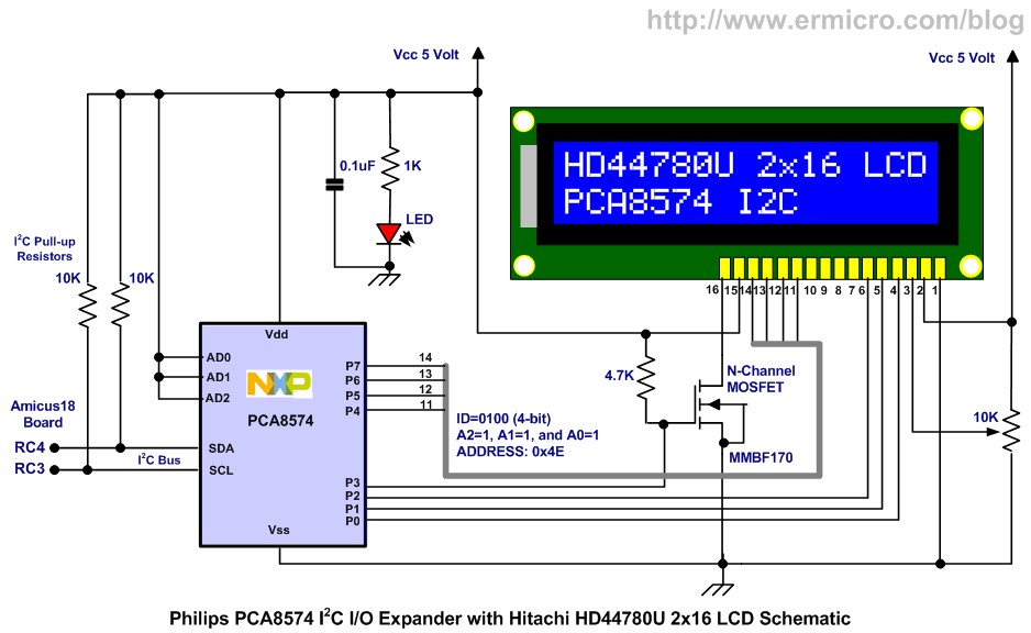
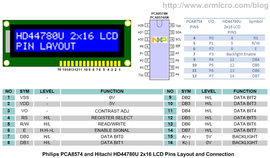
The PCA8574 I/O expander has 3-bit configurable address (000 to 111) which provides up to 7 devices that could be attached simultaneously on the same I2C bus. In this project the Philips PCA8574 8-bits I/O expander is used to control the Hitachi HD44780U (or its compatible) 2×16 LCD. The complete I2C 2×16 LCD schematic is shown on this following picture.
In this project I used the 4-bit modes of Hitachi 44780U 2×16 LCD driver to send the data from the PCA8574 I/O expander
The Philips PCA8574 SDA (Serial Data, pin 15) and SCL (Serial Clock, pin 14) are connected to the Amicus18 board SDA pin (RC4) and SCL pin (RC5). These two pins are also called the I2C bus where you could attach many of the I2C devices on the same bus. Noticed that you need 2 pull-up resistors (value between 2.2K to10K) on each of the I2C bus, these pull-up resistors is very important in the I2C bus protocol without them the I2C bus protocol will not work.
The I2C LCD Project BASIC Code
The strength of using the Amicus18 Proton BASIC from Crownhill Associates because it’s a fully compiler language, this mean your BASIC code first will be compiled into the equivalent Microchip PIC assembler code by the Proton BASIC compiler and next the Amicus18 IDE will use the Microchip MPLAB ASM (Assembler) compiler to produce a native Microchip PIC HEX code to be loaded into the PIC18F25K20 microcontroller flash program memory, therefore you need to install the Microchip MPLAB IDE first in order to use the Amicus18 development environment correctly. You could clearly see the compiling phase result when you use the Microchip MPLAB IDE to compile and debug your BASIC code using the Proton BASIC compiler.
The BASIC code starts by initializing the PORTB as a digital output using the PORTB tri-state buffer registered called TRISB to be %00000000. The PORTB is used to drive the 8 LED indicators in this project as shown on this following BASIC code:
' Initial PORTB As Digital Output
TRISB = %0000000
PORTB = %00000000
' Open the ADC Macro:
' ADC_FOSC_32 - Fosc/32
' ADC_RIGHT_JUST - Right justified for 10-bit operation
' ADC_2_TAD - TAD value of 2
' ADC_REF_VDD_VSS - Vref+ at Vcc : Vref- at Gnd
' ADC_1ANA - Use AN0 as an analogue input
'
OpenADC(ADC_FOSC_32 & ADC_RIGHT_JUST & ADC_2_TAD, ADC_REF_VDD_VSS, ADC_1ANA)
' Initial the LCD Display Here
GoSub LCD_Init
The OpenADC() macro function is used to initialized the Microchip PIC18F25K20 microcontroller ADC peripheral to read the 10K trimpot attached to the AN0 (RA0) analog port. Next we call the LCD_Init() subroutine to initial the 2×16 HD44780U LCD connected to the Philips PCA8574 I2C I/O expander. In order to communicate with the PCA8574 chip I used the Proton BASIC HBusOut command, this command will automatically use the Microchip PIC18 microcontroller Master Synchronous Serial Port (MSSP) peripheral to communicate with the I2C devices. The complete subroutine to write to the Philips PCA8574 I2C I/O expander port is implemented in Write_PCA8574 subroutine.
Write_PCA8574:
  HBStart              ' Send a Start condition
  HBusOut PCA8574_ADDR ' Send a WRITE command to PCA8574
  HBusOut I2CData      ' Send Data to PCA8574
  HBusNack             ' Send No Acknowledge to PCA8574
  HBStop               ' Send a Stop condition
  DelayUS 100          ' Put the 100us Delay Here
  Return
' EOF: Write_PC8574 Subroutine
From the Write_PCA8574 subroutine you could clearly see that in order to send a 8-bit data to the PCA8574 I2C chip, first we have to send the I2C START signal (HBStart command) follow by sending the PCA8574 address ($43, 43 in hex notation or 67 in decimal notation) using the HBusOut command. Because the I2C bus could be connected with many I2C devices, therefore every I2C devices have their own unique address to be called by the master I2C device (i.e. PIC18F25K20 microcontroller).
Next we send the actual data using the HBusOut command followed by HBusNack (send no acknowledge signal) and HBStop (send STOP signal) to tell the PCA8574 that we stop sending the data. The I2C LCD complete subroutine is implemented in LCD_PutCmd, LCD_PutCh, LCD_Init, and LCD_PutStr. You could read the complete explanation of how to drive the Hitachi 44780U 2×16 LCD on this following article AVR LCD Thermometer Using ADC and PWM Project.
Inside the infinite loop (i.e. while – wend statement) we read the 10K trimpot value using the ADC peripheral port AN0 (RA0) and use this value in a DelayMS command and display it on the 2×16 LCD. Next we display the bit shifted pattern on the 8 LED connected to the PORTB.
Now you could watch and enjoy the entire project presented here on this following video, where you could watch how we use the Amicus18 development environment and Amicus18 Proton BASIC language to interface with the I2C 2×16 LCD device.
The Final Though
The Amicus18 development environment could be consider as one of the embedded development framework that try to wrap all the “technical complexity” in developing the embedded system using the well known BASIC language, therefore it depend heavily on the “build-in” hardware function (library) that provided by the Amicus18 Proton BASIC compiler to achieve its objective (i.e. easy to use). The good things about the free Amicus18 Proton BASIC compiler that you could write your own BASIC code functions, and distribute this code to other Amicus18 users. But if you prefer to use a C language instead of a BASIC language, than the Amicus18 board could be considered as just another Microchip 28-pins PIC18F family development board with Arduino board form factor.
As I demonstrate in this project because the Amicus18 Proton BASIC compiler use the Microchip MPLAB ASM to produce the final Microchip PIC HEX code, many of the C language style operator has been adopted especially for bit manipulation (e.g. bit shifting, AND/OR, and NOT), and this make developing the embedded system with Amicus18 Proton BASIC become interesting and fun.
Bookmarks and Share


