Blog Entry
The Line Follower Robot with Texas Instruments 16-Bit MSP430G2231 Microcontroller
September 11, 2011 by rwb, under Robotics.
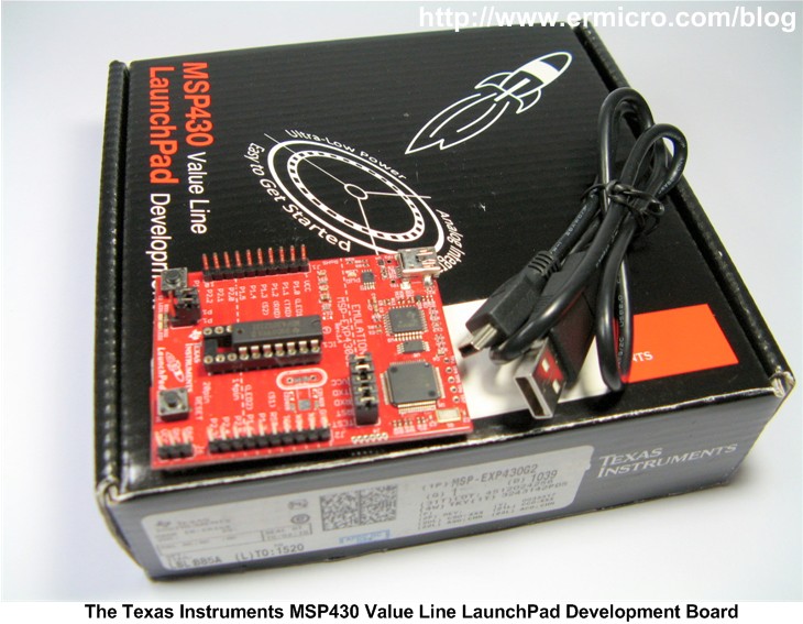
When Texas Instruments (TI) introduced their new value line 16-bit microcontroller complete with the programmer and development board named MSP430 Value Line LaunchPad in the mid of 2010 for only USD 4.30 include the shipping cost, this make it as the cheapest programmer and development board platform that you could ever find in the market. Therefore the introduction of the MSP430 value line LaunchPad development board make a tremendous impact especially among the electronics hobbyist, students, and enthusiast because now the big boy (TI) is seriously taking part in the electronic hobbyist market and directly compete their 16-bit class value line microcontrollers to the 8-bit class microcontrollers which are mostly dominated by Atmel and Microchip.
The MSP430 Value Line LaunchPad development board is come with the eclipse based Texas Instruments integrated development environment (IDE) called Code Composer Studio (downloadable from the TI website) and equiped with the professional grade C compiler and debugger, which make the development of MSP430 microcontroller based embedded system become easy and fun.
As you know most of the electronics hobbyist used the popular 8-bit class microcontroller to most of their embedded project such as AVR microcontroller from Atmel and PIC microcontroller from Microchip. Now you might wonder why we have to learn another type of microcontroller as most of the modern microcontroller has already provided all the necessary features that we need. Why not, learning another type of microcontroller is one of the fascinating and challenging topics to be learned especially for the true electronics hobbyist as this will broaden our knowledge and utilize what is the best on each of the microcontroller types to support our future embedded system project.
The MSP430 Microcontroller Project
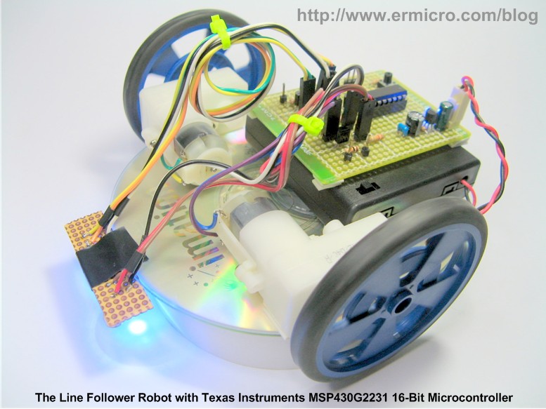
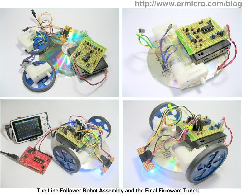
After many considerations of what is the attractive way to introduce this MSP430 microcontroller, instead of just started with a common blinking LED, I decided to built a simple and yet most popular robot,…yes,…is another Line Follower Robot (LFR) using the Texas Instruments 14 pins 16-bit MSP430G2231 microcontroller that come with the MSP430 Value Line LaunchPad development board. Because I think building a robot will give you the basic knowledge and understanding you needs to start explores many of the advance features offered by this 16-bit MSP430 value lines microcontrollers by yourself.
If you notice on the above picture this Line Follower Robot (LFR) used a similar CD chassis, DC geared motor, and sensors found on my previous articles “The LM324 Quad Op-Amp Line Follower Robot with Pulse Width Modulation“. Therefore this project also serves as a good example of the “digital” version of the analog LFR we’ve built before.
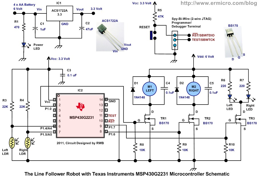
The following is the complete electronic schematic of the Line Follower Robot:
Now let list down all the necessary electronic components and other supported materials to build this LFR:
1. Resistors: 220 (2), 470 (1), 10K (3), 22K (2), and 47K (1)
2. Light Dependent Resistor (2)
3. Capacitors: 0.1uF (3), 1uF (1) and 47uF/16v (1)
4. Diodes: 1N4148 (2)
5. High Intensity 3 mm blue Light Emitting Diode (3)
6. N-Channel MOSFET: BS170 (3)
7. IC: ACS 1722A 3.3 volt voltage regulator or equivalent
8. Texas Instruments MSP430 Value Line LaunchPad Development Board
9. DC Motor: Solarbotics GM2 Geared DC motor with Wheel (2)
10. One reset push button switch
11. Perforated PCB: 70 x 55 mm for the main board and 50 x 15 mm for the sensors board
12. 4 x AA Battery holder
13. CD/DVD ROM (2)
14. Plastic Beads and Paper Clip for the castor (the third wheel)
15. Bolt, Nuts, Double Tape and Standard Electrical Tape for the black line
16. Texas Instruments Code Composer Studio Core Edition version 4.2.1.00004 (used in this project)
17. Texas Instruments MSP430G2231 microcontroller datasheet SLAS694 and SLAU144F.
The complete firmware for this Line Follower Robot project is developed with the C language:
/*****************************************************************************
//  File Name    : LineFollower.c
//  Version      : 1.0
//  Description  : The MSP430G2231 Line Follower Robot
//  Author       : RWB
//  Target       : MSP430G2231 Custom Line Follower Board
//  Compiler     : Code Composer Studio Version: 4.2.1.00004
//  IDE          : Code Composer Studio Version: 4.2.1.00004
//  Programmer   : Texas Instruments MSP430 Launchpad Board
//  Last Updated : 16 Aug 2011
*****************************************************************************/
#include <msp430g2231.h>
#define LEFT_MOTOR BIT0
#define RIGHT_MOTOR BIT6
#define LEFT_LDR BIT4
#define RIGHT_LDR BIT5
#define SENSOR_LED BIT7
#define MAX_COUNT 100
// Sensor Calibration
#define CAL_SAMPLES 5
#define CAL_SPEED1 75
#define CAL_SPEED2 40
#define CAL_MOVE_DELAY 320
// PWM Duty Cycle Threshold
#define MAX_THRESHOLD 75
#define MIN_THRESHOLD 60
// Sensor Status
#define LEFT_SENSOR 0
#define RIGHT_SENSOR 1
unsigned int pwm_count=0;
unsigned int pwm_m1=0;
unsigned int pwm_m2=0;
unsigned int min_leftLDR=0;
unsigned int max_leftLDR=0;
unsigned int min_rightLDR=0;
unsigned int max_rightLDR=0;
unsigned int adc2cycle(unsigned int adc, unsigned int in_min, unsigned int in_max)
{
  unsigned int adc_val;

  // Calculate the result and put it within 0 to 100% PWM Duty Cycle value
  adc_val = 100 - ((adc - in_min) * 100 / (in_max - in_min));
  if (adc_val <= MIN_THRESHOLD)
     adc_val=0;
  if (adc_val >= MAX_THRESHOLD)
     adc_val=MAX_THRESHOLD;
  return(adc_val);
}
void DelayMs(unsigned int ms)
{
  while(ms--) {
    __delay_cycles(1000);     // 1 ms delay for 1 MHz Internal Clock
  }
}
// TimerA Channel 0 interrupt service routine
#pragma vector=TIMERA0_VECTOR
__interrupt void Timer_A (void)
{
  // The PWM Period is about: 101 x 0.1 ms = 10.1 ms
  pwm_count++;
  if (pwm_count >= MAX_COUNT) {
    pwm_count=0;
    P1OUT |= LEFT_MOTOR;      // Turn On Left Motor
    P1OUT |= RIGHT_MOTOR;     // Turn On Right Motor
  }
  if (pwm_count == pwm_m1) {
    P1OUT &= ~LEFT_MOTOR;     // Turn Off Left Motor
  }

  if (pwm_count == pwm_m2) {
    P1OUT &= ~RIGHT_MOTOR;    // Turn Off Right Motor
  }
}
unsigned int ReadSensor(unsigned char chn_stat)
{
  ADC10CTL0 &= ~ENC;	            // Disable ADC10
  if (chn_stat) {
  	ADC10CTL1 &= ~INCH_4;  	        // Deselect ADC Channel 4
    ADC10CTL1 |= INCH_5;            // Select ADC Channel 5 (A5), Right LDR
  } else {
  	ADC10CTL1 &= ~INCH_5;           // Deselect ADC Channel 5
    ADC10CTL1 = INCH_4;             // Select ADC Channel 4 (A4), Left LDR
  }
  ADC10CTL0 |= ENC + ADC10SC;       // Enable ADC10 and Conversion start
  while (ADC10CTL1 & ADC10BUSY);    // Wait for ADC Conversion
  return(ADC10MEM); 	            // Return ADC Value
}
void CalibrateSensor()
{
  unsigned char i;
  unsigned int tmp_left,tmp_right;

  // Get the Maximum Value Sensor Value (over black line)
  P1OUT |= SENSOR_LED;                      // Turn On the Sensor LED
  DelayMs(1000);                            // Give enough time to light the LDR

  tmp_left=0;
  tmp_right=0;
  for(i=0; i < CAL_SAMPLES; i++) {
    tmp_left += ReadSensor(LEFT_SENSOR);    // Read The Left LDR (A4)
    __delay_cycles(50);
    tmp_right += ReadSensor(RIGHT_SENSOR);  // Read The Right LDR (A5)
    __delay_cycles(50);
  }
  max_leftLDR = tmp_left / CAL_SAMPLES;     // Get the Max Left Average Value
  max_rightLDR = tmp_right / CAL_SAMPLES;   // Get the Max Right Average Value

  // Now move the robot to the next calibration stage
  pwm_m1=CAL_SPEED1;
  pwm_m2=CAL_SPEED2;
  DelayMs(CAL_MOVE_DELAY);

  // Turn off the Motor (Duty Cycle 0)
  pwm_m1=0;
  pwm_m2=0;

  // Get the Minimum Value Sensor Value (over white line)
  tmp_left=0;
  tmp_right=0;
  for(i=0; i < CAL_SAMPLES; i++) {
    tmp_left += ReadSensor(LEFT_SENSOR);    // Read The Left LDR (A4)
    __delay_cycles(50);
    tmp_right += ReadSensor(RIGHT_SENSOR);  // Read The Right LDR (A5)
    __delay_cycles(50);
  }
  min_leftLDR = tmp_left / CAL_SAMPLES;     // Get the Min Left Average Value
  min_rightLDR = tmp_right / CAL_SAMPLES;   // Get the Min Right Average Value

  // Blink the Sensor LED after calibrating
  for(i=0; i < CAL_SAMPLES; i++) {
    P1OUT &= ~SENSOR_LED;                   // Turn Off LED
    DelayMs(500);
    P1OUT |= SENSOR_LED;                    // Turn On LED
    DelayMs(30);
  }
}
void main(void)
{
  unsigned int sensor_val;

  WDTCTL = WDTPW + WDTHOLD;                 // Stop WDT

  // P1.0,P1.6 and P1.7 output, Other as Input
  P1DIR = LEFT_MOTOR + RIGHT_MOTOR + SENSOR_LED;
  // Enable the pull-down resistor on the unused input ports
  P1REN = BIT1 + BIT2 + BIT3;
  P2REN = BIT6 + BIT7;
  // Reset all the Output
  P1OUT = 0x00;

  // TIMER A channel 0 will interrupt every 100 cycles
  // Interrupt time counter period: 100 / 1.000.000 = 0.1 ms
  TACCTL0 = CCIE;                           // CCR0 interrupt enabled
  TACCR0 = 99;
  TACTL = TASSEL_2 + MC_1;                  // Start Timer, SMCLK, Up Mode

  // Start the ADC10 Peripheral
  // Vref = Vcc, 16 ADC Clock, Enable ADC10
  ADC10CTL0 = SREF_0 + ADC10SHT_3 + ADC10ON;

  // Sample-and-hold ADC10SC bit, ADC10 Clock /1, ADC10 Source Clock, Single Channel Conversion
  ADC10CTL1 = SHS_0 + ADC10DIV_0 + ADC10SSEL_0 + CONSEQ_0;
  ADC10AE0 = LEFT_LDR + RIGHT_LDR;          // Enable A4 and A5 as ADC Input
  DelayMs(1);                               // Wait for ADC Ref to settle

  // Initial the PWM Duty Cycle and Enable the MSP430 Interrupts
  pwm_count=0;
  pwm_m1=0;
  pwm_m2=0;
  __enable_interrupt();

  // Now we Calibrate the LDR Sensors
  CalibrateSensor();
  DelayMs(1000);                            // Delay 1000 ms before start

  // Loop Forever
  for(;;) {
  	// Read the Left LDR Sensor and make sure is within the range
  	sensor_val=ReadSensor(LEFT_SENSOR);
  	if (sensor_val > max_leftLDR)
  	  sensor_val=max_leftLDR;
  	if (sensor_val < min_leftLDR)
  	  sensor_val=min_leftLDR;

  	// Assigned the Left PWM Duty Cycle
  	pwm_m1=adc2cycle(sensor_val,min_leftLDR,max_leftLDR);
  	__delay_cycles(20);

  	// Read the Right LDR Sensor and make sure is within the range
  	sensor_val=ReadSensor(RIGHT_SENSOR);
  	if (sensor_val > max_rightLDR)
  	  sensor_val=max_rightLDR;
  	if (sensor_val < min_rightLDR)
  	  sensor_val=min_rightLDR;

  	// Assigned the Right PWM Duty Cycle
  	pwm_m2=adc2cycle(sensor_val,min_rightLDR,max_rightLDR);
  	__delay_cycles(20);
  }
}
/* EOF: LineFollower.c */
The Line Follower Robot Working Principle
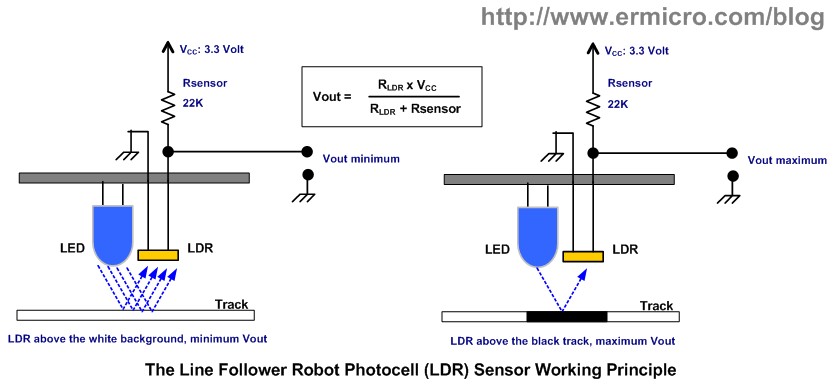
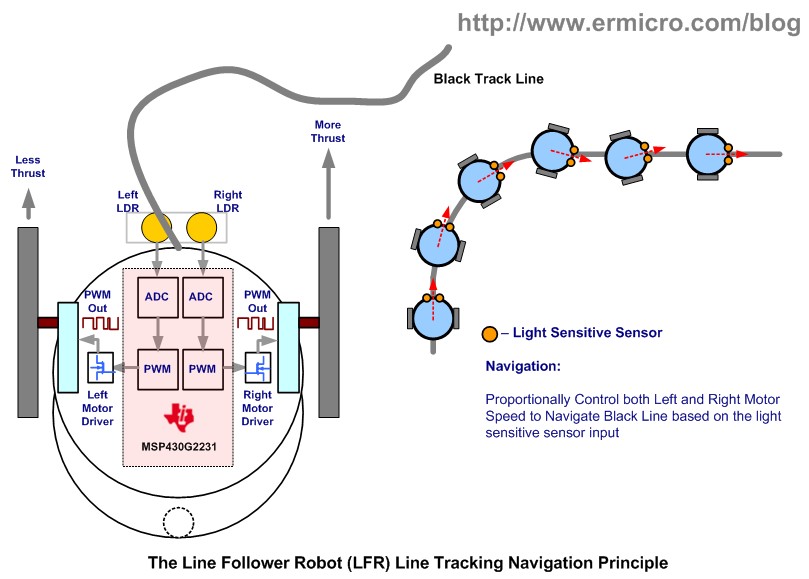
This Line Follower Robot design used the photocell sensor known as a Light Dependent Resistor (LDR) made from Cadmium Sulphide (CdS) to detect the black track line, when the LDR is above the black track line it will give a high resistance value while above the white background and it will give a low resistance value. Together with the 22K resistor, they will form what’s known as the voltage divider circuit. This voltage divider circuit sensor will provide the varying voltage according to the amount of the light intensity reflected back to the LDR. The blue Light Emitting Diode (LED) will provide a constant light source for the sensors.
Next the MSP430G2231 microconttroller will translate this varying voltage using its analog to digital conversion (ADC) peripheral into the DC motor rotation speed using what known as the Pulse Width Modulation (PWM) signal. Because this LFR used the “differential steering” (i.e. used two independent DC motor for steering) method, therefore by varying the left and the right DC motor rotation speed proportionally to the light intensity received by both of the left and right LDR, we could easily make the robot to navigate the black track line successfully.
The MSP430G2231 Microcontroller
The Mixed Signal Processing (MSP) 430 series microcontroller is first introduced in the late of 1990 by Texas Instruments. It’s a 16-bit RISC (reduced instruction set computer) microcontroller with Von Neumann architecture where the CPU, I/O, and memory shared the same 16-bit control, address, and data bus. The MSP430 is specially design for low consumption and optimize to be used with the C compiler.
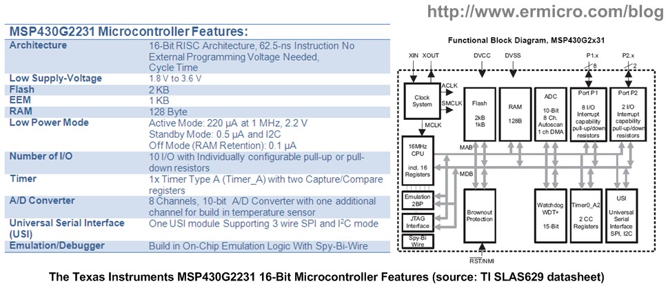
The “G” value line series such as the 14-pin MSP430G2231 microcontroller is introduced together with the price phenomenal LaunchPad development board. This microcontroller has these following interesting features which I’m sure as the electronics hobbyist you will eager to try it by yourself.
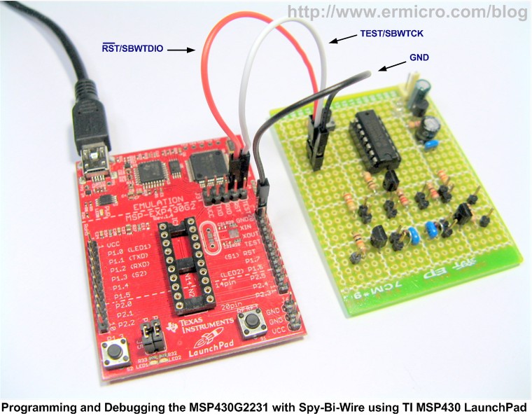
One of the features that make this 14-pin MSP430G2231 microcontroller special is the build in on-chip emulation logic using what is called “Spy-Bi-Wire” or also known as 2-wire JTAG (Joint Test Action Group). This useful feature enables us to step the C code line by line, set a break point, and check the variables or registers value while the chip is in the circuit (in circuit programming and debugging).
The MSP430G2231 Microcontroller Input/Output (I/O)
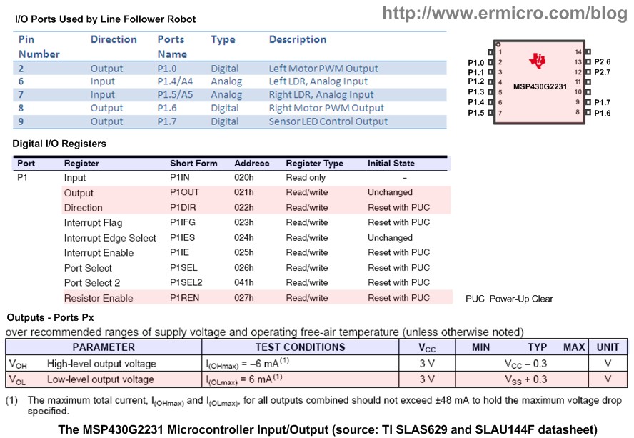
The MSP430G2231 microcontroller has 10 I/O, 8 pins on the first ports (P1) and 2 pins on the second ports (P2). All these ports are configurable as the general purpose input or output ports and often they multiplexed with other I/O function such as A/D (analog to digital) input, PWM out, USI (Universal Serial Interface), Clock Input, Crystal Oscillator Input, and JTAG I/O terminal.
As you’ve seen from the table above, the LFR only used several I/O ports and as rules of thumb the unused I/O ports have to be configured as the output ports and leave them unconnected. Alternatively you could configure all the unused ports as the input ports (default on power-up reset) and enable the pull-down resistor in order to avoid the unpredictable “floating” inputs problem arise in your project. The following C code shows how to configure the necessary I/O ports for this LFR:
#define LEFT_MOTOR BIT0
#define RIGHT_MOTOR BIT6
#define LEFT_LDR BIT4
#define RIGHT_LDR BIT5
#define SENSOR_LED BIT7
...
// P1.0,P1.6 and P1.7 output, Other as Input
P1DIR = LEFT_MOTOR + RIGHT_MOTOR + SENSOR_LED;
// Enable the pull-down resistor on the unused input ports
P1REN = BIT1 + BIT2 + BIT3;
P2REN = BIT6 + BIT7;
// Reset the Output
P1OUT = 0x00;
The P1DIR (port 1 direction) register is used to configure the I/O port direction, where each bit of this 16-bit corresponding to the I/O ports (P1.0 to P1.7). By enabling the corresponding bit we simply tell the MSP430G2231 microcontroller to configure the port as an output port. Next the P1REN (port 1 pull-up/pull-down resistor) register, by enabling the corresponding bit we could enable the pull-down resistor (configured as input) or pull-up resistor (configured as output).
The MSP430G2231 microcontroller P1OUT (port 1 output) register is used to control the output port logical state, it used to turn on and off the P1.0 and P1.6 to generate the required PWM signal. I used these ports because these ports are connected with two LED in the MSP430 LaunchPad development board, therefore you could easily test the PWM output using these LEDs. The P1.7 output port is also used to control the sensor LED; beside as the sensor light source, it also serves as a sign indicator when the LFR finish calibrating the sensors. The following code use C language bit operator to turn on and off the port using the MSP430G2231 microcontroller P1OUT register:
// Reset all the Output
P1OUT = 0x00;
...
...
P1OUT |= LEFT_MOTOR;      // Turn On Left Motor
P1OUT |= RIGHT_MOTOR;     // Turn On Right Motor
...
...
P1OUT &= ~LEFT_MOTOR;     // Turn Off Left Motor
...
...
P1OUT &= ~RIGHT_MOTOR;    // Turn Off Right Motor
...
...
P1OUT &= ~SENSOR_LED;     // Turn Off LED
...
P1OUT |= SENSOR_LED;      // Turn On LED
...
...
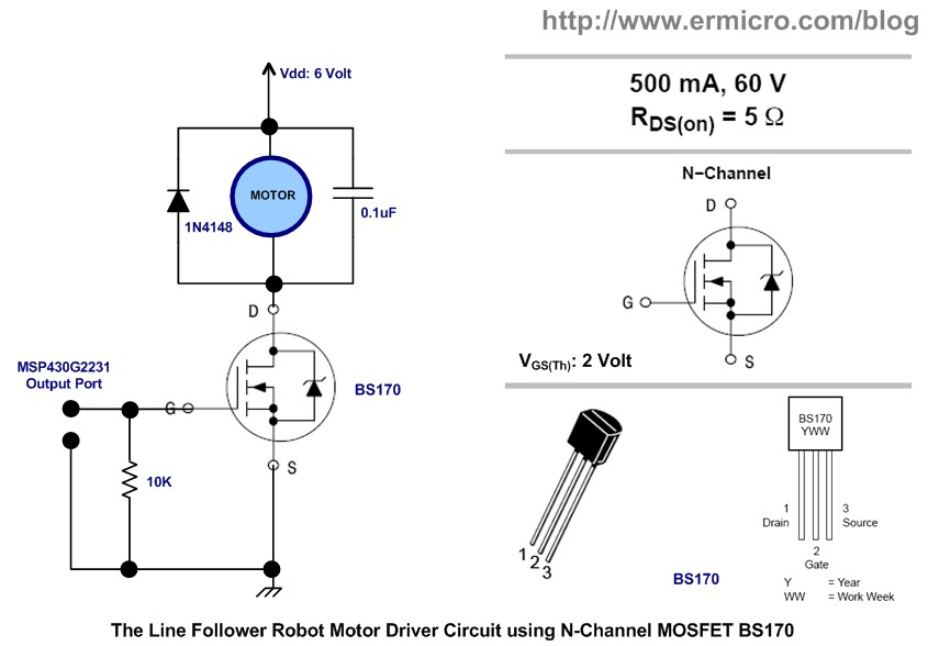
From the data sheet the maximum output current for each port is about 6 mA and for all outputs combined is about 48 mA, this of course is not suitable for driving the DC motor directly; therefore in this project I used the n-channel MOSFET (Metal Oxide Semiconductor Field Effect Transistor) BS170 to drive the DC motor and sensor LED. The advantage of using MOSFET because this type of transistor has very high input impedance on its Gate (G) terminal which mean its need very low current in order to operate and its has a low ON resistance between the its Drain (D) and Source (S) terminals called Rds especially when operate on higher DC voltage supply compare to the ordinary Bipolar Junction Transistor (BJT).
By applying voltage greater than the Vgs threshold voltage i.e. voltage applied between the Gate and Source terminal, it’s about 2 volt on the BS170 MOSFET, we could bring the MOSFET into its saturate stage (ON) and this voltage level could be easily provided by the MSP430G2231 microcontroller output port.
The MSP430G2231 Pulse Width Modulation
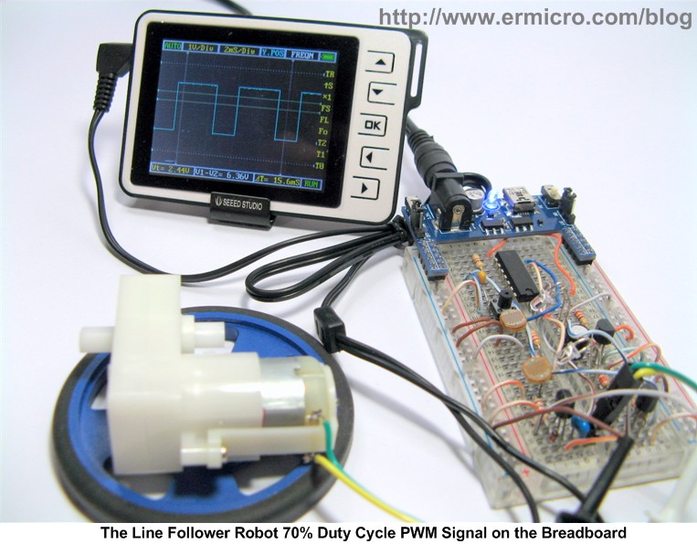
Pulse Width Modulation (PWM) is a technique widely used in modern switching circuit to control the amount of power given to the electrical device (i.e. the DC motor). By simply switches ON and OFF the power supplied to the DC motor rapidly and the average amount of energy received by the DC motor is corresponding to the ON and OFF period (duty cycle); therefore by varying the ON period i.e. longer or shorter than the OFF period, we could control the DC motor rotation speed.
The MSP430G2231 microcontroller actually has two capture/compare registers that could be used for generating the PWM automatically, but because we need two independent PWM sources with the configurable PWM duty cycle and on the specific PWM frequency, therefore we could not use the built in PWM which is provided by the MSP4302231 microcontroller. Instead on this LFR project I used the software PWM which is based on the MSP430G2231 Timer_A channel 0 interrupt.
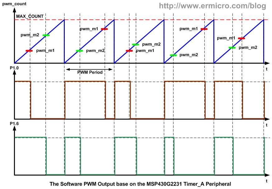
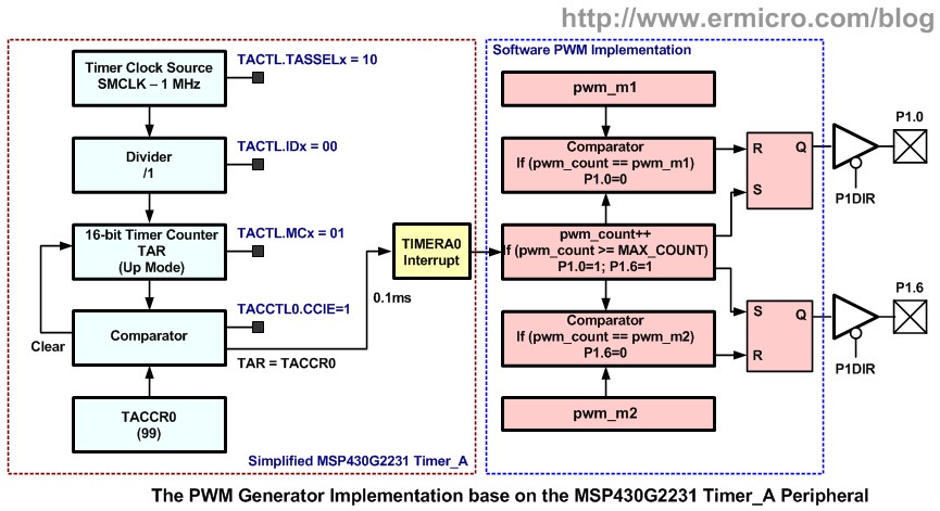
The basic software PWM could be made by first creating the basic digital ramp counter for the PWM signal period and then use the variable to be compared with the ramp counter value and this will create the necessary PWM duty cycle as shown on this following diagram:
The basic digital ramp counter used the pwm_count variable to count from 0 to MAX_COUNT and start to count from 0 again repeatedly. The pwm_count will provide a constant period to the PWM signal. Next we need two variables pwm_m1 and pwm_m2 to be compared with the pwm_count variable. When the pwm_count reach 0, we simply turn ON the MSP430G2231 microcontroller output port and when the pwm_count equal to the pwm_m1 or pwm_m2 value, we simply turn OFF the MSP430G2231 microcontroller output port. Therefore by varying both of the pwm_m1 or pwm_m2 variables value we could control the PWM signal duty cycle.
We used the MSP430G2231 microcontroller Timer_A in “Up Mode” to actually increase and control the pwm_count value and when the Timer_A counter register (TAR) equal to Timer A Capture/Control Register channel 0 (TACCR0) it will generate the interrupt. Because on this project I used MSP430G2231 microcontroller standard Sub Main Clock (SMCLK) of 1 MHz for the Timer_A clock source, thus assigning 99 to the TACCR0 register will make the Timer_A channel 0 to generate interrupt on every 100 (TACCR0 + 1) cycles or about 0.1 ms as shown on this following C code:
// TIMER A channel 0 will interrupt every 100 cycles
// Interrupt time counter period: 100 / 1.000.000 = 0.1 ms
TACCTL0 = CCIE;                           // CCR0 interrupt enabled
TACCR0 = 99;
TACTL = TASSEL_2 + MC_1;                  // Start Timer, SMCLK, Up Mode
The software PWM implementation is implemented inside the Timer_A channel 0 interrupt function handler as show on this following C code:
// TimerA Channel 0 interrupt service routine
#pragma vector=TIMERA0_VECTOR
__interrupt void Timer_A (void)
{
  // The PWM Period is about: 101 x 0.1 ms = 10.1 ms
  pwm_count++;
  if (pwm_count >= MAX_COUNT) {
    pwm_count=0;
    P1OUT |= LEFT_MOTOR;      // Turn On Left Motor
    P1OUT |= RIGHT_MOTOR;     // Turn On Right Motor
  }
  if (pwm_count == pwm_m1) {
    P1OUT &= ~LEFT_MOTOR;     // Turn Off Left Motor
  }

  if (pwm_count == pwm_m2) {
    P1OUT &= ~RIGHT_MOTOR;    // Turn Off Right Motor
  }
}
By choosing MAX_COUNT of 100, we could get the PWM period about 101 x 0.1ms, which is about 10.1 ms or we could say that the PWM frequency is about 100 Hz and by assigning each of the pwm_m1 and pwm_m2 variables value from 0 to 100, we could get the PWM duty cycle output varying from 0 to 100%.
The pwm_m1 and pwm_m2 variables value is supplied by the digital value from the left and the right sensors from the adc2cycle() function which basically set the upper and lower PWM duty cycle value returned to these variables. The upper and lower threshold setting is depend on the black line track and the sensors characteristic and could be changed by changing each of the MAX_THRESHOLD and the MIN_THRESHOLD definition value.
The MSP430G2231 ADC Peripheral
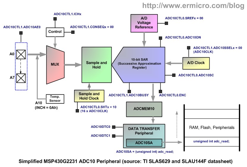
The MSP430G2231 microcontroller has one 10-bit Analog to Digital Conversion (ADC) peripheral also known as ADC10 peripheral with 8 channel (A0 to A7), where the channel (A10) is specially used for the internal thermometer. The MSP430G2231 ADC10 peripheral used what is called “Successive Approximation Method” to convert the analog input from one of these channels to the 10-bit digital representation and stores the result in the ADC10MEM register.
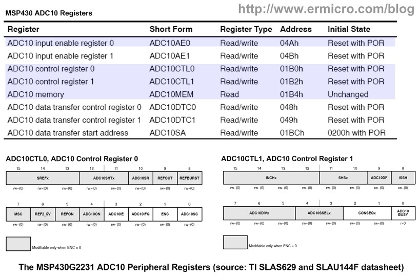
The ADC10 peripheral is controlled by two control registers, ADC10CTL0 and ADC10CTL1. Thus by setting the ADC10ON bit (logical high) in ADC10CTL0 register we enable this ADC core. The most important thing to remember that these ADC10 control registers can only be modified when ENC (Enable Conversion) bit in ADC10CTL0 is low (ENC = 0) and prior to the A/D conversion this bit has to be set to 1 (logical high).
The MSP430G2231 ADC10 peripheral have four operating mode which could be selected by setting the CONSEQx bits in the ADC10CTL1 (ADC10 Control Register 1) and on this LFR project we will use the “Single Channel Single Conversion Mode“. The following C code show how we setup the MSP430G2231 microcontroller ADC10 peripheral:
// Start the ADC10 Peripheral
// Vref = Vcc, 16 ADC Clock, Enable ADC10
ADC10CTL0 = SREF_0 + ADC10SHT_3 + ADC10ON;

// Sample-and-hold ADC10SC bit, ADC10 Clock /1, ADC10 Source Clock, Single Channel Conversion
ADC10CTL1 = SHS_0 + ADC10DIV_0 + ADC10SSEL_0 + CONSEQ_0;
ADC10AE0 = LEFT_LDR + RIGHT_LDR;          // Enable A4 and A5 as ADC Input
DelayMs(1);                               // Wait for ADC Ref to settle
The multiplexer analog channels input could be selected by assigning the corresponding INCHx bits in the ADC10CTL1 register. The actual A/D conversion is take placed in the ReadSensor() function, as shown on this following C code:
unsigned int ReadSensor(unsigned char chn_stat)
{
  ADC10CTL0 &= ~ENC;	             // Disable ADC10
  if (chn_stat) {
    ADC10CTL1 &= ~INCH_4;  	     // Deselect ADC Channel 4
    ADC10CTL1 |= INCH_5;            // Select ADC Channel 5 (A5), Right LDR
  } else {
  	ADC10CTL1 &= ~INCH_5;           // Deselect ADC Channel 5
    ADC10CTL1 = INCH_4;             // Select ADC Channel 4 (A4), Left LDR
  }
  ADC10CTL0 |= ENC + ADC10SC;       // Enable ADC10 and Conversion start
  while (ADC10CTL1 & ADC10BUSY);    // Wait for ADC Conversion
  return(ADC10MEM); 	              // Return ADC Value
}
Noticed on the C code above that before we change the ADC10 control register (i.e. ADC10CTL0 and ADC10CTL1), we have to disable the ADC10 first be resetting the ENC bit on ADC10CTL0 register then prior to the A/D conversion we set (enable) the ENC and ADC10SC (ADC10 Start Conversion) bits in ADC10CTL0 register. Next we wait the conversion by checking the ADC10BUSY bit on the ADC10CTL1 register. When the ADC10BUSY bit is become “0” means the conversion is done and we could retrieve the stored 10-bit digital value in the ADC10MEM register.
One of the most important features on this LFR project is the used of the calibration phase in the CalibrateSensor() function. In the calibration phase we read the sensors for their maximum value (i.e. on the black line) and the minimum (i.e. on the white background) value. This calibration phase will ensure both of the left and right sensors provide equal value to the PWM generator for driving DC motor. The actual algorithm to make this LFR navigate the black track line successfully is shown on this following C code:
// Loop Forever
for(;;) {
	// Read the Left LDR Sensor and make sure is within the range
  	sensor_val=ReadSensor(LEFT_SENSOR);
  	if (sensor_val > max_leftLDR)
  	  sensor_val=max_leftLDR;
  	if (sensor_val < min_leftLDR)
  	  sensor_val=min_leftLDR;

  	// Assigned the Left PWM Duty Cycle
  	pwm_m1=adc2cycle(sensor_val,min_leftLDR,max_leftLDR);
  	__delay_cycles(20);

  	// Read the Right LDR Sensor and make sure is within the range
  	sensor_val=ReadSensor(RIGHT_SENSOR);
  	if (sensor_val > max_rightLDR)
  	  sensor_val=max_rightLDR;
  	if (sensor_val < min_rightLDR)
  	  sensor_val=min_rightLDR;

  	// Assigned the Right PWM Duty Cycle
  	pwm_m2=adc2cycle(sensor_val,min_rightLDR,max_rightLDR);
  	__delay_cycles(20);
}
The Line Follower Robot Assembly
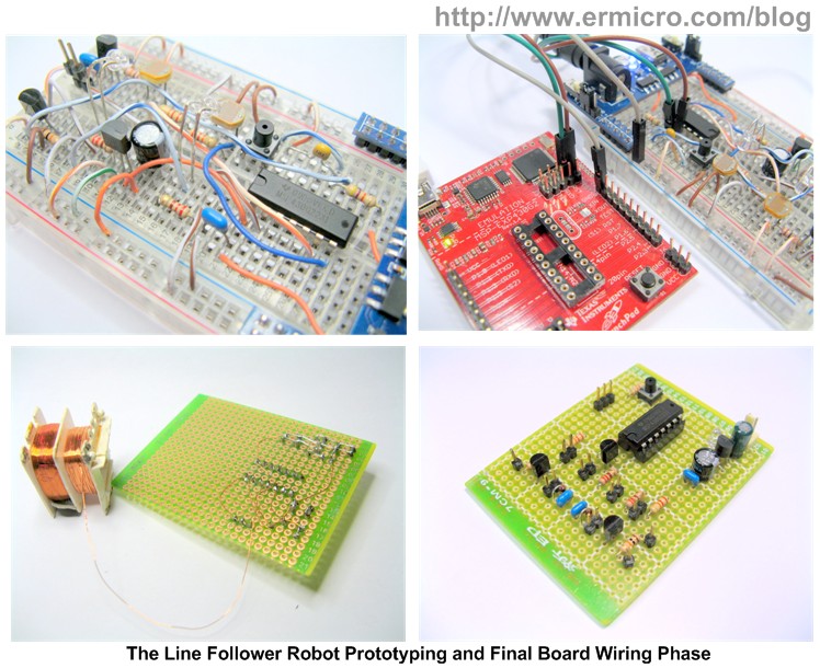
The Line Follower Robot first is constructed on the breadboard in order to test the circuit before I move it to the perforated PCB (70 x 55 mm); I used a similar wiring method to wire the circuit on the main LFR perforated PCB as explained on my previous article “Quick and Efficiently Wiring Your Prototype Circuit Board“.
The Line Follower Robot construction could be constructed freely but the easiest one is to use the discarded CD/DVD ROM as shown on these following pictures:
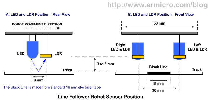
I glued the two CDROM together in order to make more room and attached the two GM2 DC motors, 4xAA battery holder, main board, and sensor board using the double tape. The sensors (LDR and LED) are constructed in a small perforated PCB (50 x 15 mm) with this following guidance:
Finally using the Texas Instruments MSP430 Value Line LaunchPad development board Spy-Bi-Wire connector and the Texas Instruments Code Composer Studio Core Edition v4.2.1.00004 (used in this project), we could easily programming and debugging the LFR firmware:
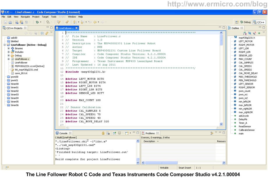
After putting all the parts together and downloading the code into the MSP430G2231 microcontroller flash RAM now is time to watch how this nice Line Follower Robot in action:
Another interesting video of this MSP430G2231 based Line Follower Robot:
The Final Thought
As you’ve seen from the demo video above this Texas Instruments 16-bit MSP430G2231 microcontroller based Line Follower Robot design could handle and smoothly navigate the complex black track line using just two LDR sensors. I hope this Line Follower Robot project will trigger your passion to learn more about this powerful 16-bit MSP430 value line series microcontroller from Texas Instruments.
Bookmarks and Share


Related Posts
31 Responses to “The Line Follower Robot with Texas Instruments 16-Bit MSP430G2231 Microcontroller”
Comment by rwb.
“The upper and lower threshold setting is depend on the black line track and the sensors characteristic and could be changed by changing each of the MAX_THRESHOLD and the MIN_THRESHOLD definition value”. You could start by using similar value used in the C code and experiment with it.
Comment by domz_rockz.
How to build a line follower robot with obstacles using MSP430???
Comment by rwb.
The principle is the same as line follower where the obstacle is the area outside the black line. For other obstacles you need to use other type of sensor for example a distance sensor (e.g. sonar or infrared) for detecting object surrounding the robot.
Comment by Cereb.
Hi…..I want to ask that is there any way to speed up this bot….and will this bot design be accurate at 90 degree or less than 90 degree turns……..plz rply fast…thanks
Comment by Cereb.
thanks for the reply……can you give me some hint that how many sensors do i need in order to make the bot accurate at tough turns……and some tips to optimize the algorithm(code) for better speed…..thanks
Comment by rwb.
You could read more about line follower robot on this following article:
Build Your Own Microcontroller Based PID Control Line Follower Robot (LFR) – Second Part
Comment by dony.
from where did u get this formula: adc_val = 100 – ((adc – in_min) * 100 / (in_max – in_min));
if a have an qtr-8A sensors (pololu) what is my Max_Threshold & Min_Threshold ? (I can’t find it in characteristics).
Comment by rwb.
It’s a standard formula to map the larger value range and convert it between the 0 to 100 value range. About the Pololu sensor you should ask the supplier.
Comment by nhatmusic.
Hi rwb, I have read your two articles about line follower robot. In this project, making a LFS with msp430. I have done as your instruction. However, i don’t know why there is always one wheel running…Please help me! thank you so much.
Comment by rwb.
Make sure you check and recheck the connection, try to swap the left and the right motor driver connection.
Comment by Riz.
HI rwb,
very nice and impressive work 🙂
dear i want this development kit(MSP430g2231),
do you have any site or possible way to order this kit online, so please tell me.
Thank you So much 🙂 in advance 🙂
Comment by UA61.
i am doing your project but i have some problems.i am using msp430G2553.its moving while calibrating and how can i change frequency for do it more slower? i wanna do it slower because my car has got some perception problems, its going out of the black line. can u help me please 🙂
Comment by rwb.
You need to adjust the PWM duty cycle in adc2cycle() function. For example instead of 0 to 100% change to 0 to 70%.
Comment by UA61.
so how can i change motors speed while turning? for example i wanna left motor’s speed faster than yours while turning. how can i adjust it?
thank you so much…
Comment by rwb.
To make the left motor (M1) speed faster, you need to adjust the value of pwm_m1 variable, for example let say the value returned by the adc2cycle() function is 60, to make it faster you just add 20 to this value. This make the PWM value for the left motor become 80% and it make the left motor rotate faster.
Comment by UA61.
Can i ask you a last question? 🙂 my last problem is my robot doesnt stop while calibrating sensors.i did same to your program. what should i do for stop motors while calibrating?? help me last time :))
Comment by UA61.
When i reset P1.0 dc motor continues to run what should i do for stop it ?
Comment by rwb.
The motor should stop during calibration as the PWM is 0% (pwm_m1=0 and pwm_m2=0). If the motors don’t stop then you have to recheck your circuit connection and program.
Comment by UA61.
I checked the circuit connection and the program , the motor stops during calibration but when the motors stop during calibration then don’t start to run automatically but the sensors detect the black line.I trigger the motor with my hand then starts to run.Why this could happen? Thanks for your help.
Comment by rwb.
It seems your motor didn’t get enough power to start, try to increase the MAX_THRESHOLD and MIN_THRESHOLD value.
Comment by ckaru2000.
Dear Sir,
Thank you for the interesting program. When I tried to build using the ccs5.4 version, I encountered the following 7 warnings. Please help me how to overcome the errors. Message Truncated…
Comment by rwb.
The CCS5.4 should compile without error, make sure you select the MSP430 when installing the CCS5.4. You will get this following message when compiling with CCS5.4:
**** Build of configuration Debug for project LineFollower ****
“C:\\ti\\ccsv5\\utils\\bin\\gmake” -k all
‘Building file: ../LineFollower.c’
‘Invoking: MSP430 Compiler’
“C:/ti/ccsv5/tools/compiler/msp430_4.1.5/bin/cl430″ -vmsp -g –define=__MSP430G2231__ –include_path=”C:/ti/ccsv5/ccs_base/msp430/include” –include_path=”C:/ti/ccsv5/tools/compiler/msp430_4.1.5/include” –diag_warning=225 –printf_support=minimal –preproc_with_compile –preproc_dependency=”LineFollower.pp” “../LineFollower.c”
‘Finished building: ../LineFollower.c’
Comment by SadawarteAbhi.
i have msp430G2553 launchpad….. and i want to burn another msp430G2xx ic which mounted on another pcd i.e. my line follower robo pcb
so which pins i have to use if the launchpad so i can program that ic using launchpad…..what should be the procedure…..???
plz reply as soon as possible
thank you.
Comment by rwb.
Read the article,… as this project used MSP430 launchpad to program the MSP430 microcontroller attached on custom PCB.
Comment by Sowmya.
I have P55NF06 nMOSFET instead of BS170.
What resistor value I should use now at gate?
I have IR sensors instead of LDR sensors.
What resistor values I should use now?
Please help. It s urgent.
Comment by rwb.
You could use similar resistor value for P55NF06 nMOSFET, If you change the LDR sensor to IR sensors you will need to change the program as it use the LDR value (ADC) to drive the LFR
Comment by mertmusatemel.
I tried this code on IAR WorkBench and it gave this”Error[Pe020]: identifier “ADC10AE0″ is undefined” and 22 error like this.
What must I do for solve this problem?
Thanks for your share.
Comment by cdboar.
This is a great article, very well written, super helpful. Thank you!
I used this to help me build my own MSP430G based Line following robot. I love the MSP430G microcontrollers!
On the whole its gone well, except I am unable to get my motors to turn enough to get the platform to move. After some fault finding and searching online, the problem seems to be that the logical voltage from the MSP of 3.3V is not enough to saturate the MOSFET gate and so the motors will turn but not sufficiently hard enough. When I place 6v onto the gate directly, the motors turn full strength. So now I am using a couple of NPN signal transistors to act as a driver (step the voltage up) to boost the gate voltage to a full (or close to) 6v. This seems to overcome my issue. I was surprised this did not effect you too, but perhaps a different motor, different wheels or differences in your MOSFETs (mine are Fairchild BS170 MOSFET N-CH 60V 500MA TO-92).
Wanted to post this in case someone else finds this great post and hits a similar problem to me.
Thanks again


Comment by JayPatel.
How to give value to MIN_THRESHOLD & MAX_THRESHOLD??