Blog Entry
Make Your Own Arduino Shield Cradle
July 3, 2011 by rwb, under Microcontroller.
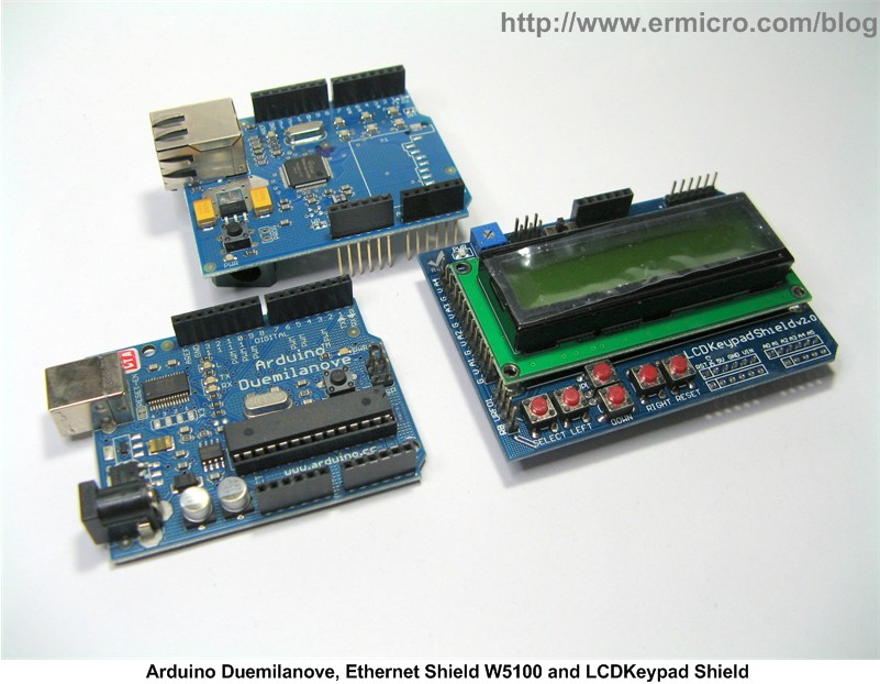
One of the advantages with the open source software and hardware such as Arduino (based on Atmel 8-bit AVR ATMega328 microcontroller) is the enormous “add-on” hardware called “Arduino Shield” that we could easily expand the Arduino main board and turn it into many cool and useful embedded system applications e.g. DC motor controller, web server, wireless application, GSM/GPRS modem and many more. The Arduino framework is so popular that many vendors come with their new Arduino shield module design almost every year.
The enormous variety of the Arduino shield hardware in the market also trigger other vendor to take advantage of this condition and start to make their own “Arduino like” main board using other type of microcontroller such as Microchip PIC 8-bits PIC18F25K20 microcontroller (Amicus18), Atmel 32-bit ARM7 AT91SAM7X512 microcontroller (netduino), STMicroelectronics 32-bits ARM Cortex M3 STM32F103RB microcontroller (Leaf Maple), NXP 32-bits ARM7 LPC2387 microcontroller (FEZ Panda), etc.
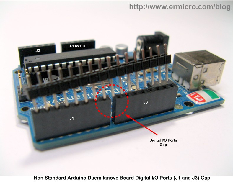
But unfortunately there is one “hick-up” on the Arduino main board design, at a glimpse you will think that this Arduino shield hardware will perfectly feed on the standard prototype board or breadboard,… hmmm… you could clearly see from this picture bellow that the digital I/O port’s gaps (J1 and J3 also called digital 1 and digital 2) in the Arduino main board is deliberately not designed for this purpose in mind. On the contrary the analog (J2) and POWER ports meets the standard gap width. This mean we could not use and plug any standard Arduino shield hardware directly into the prototype board.
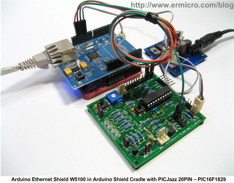
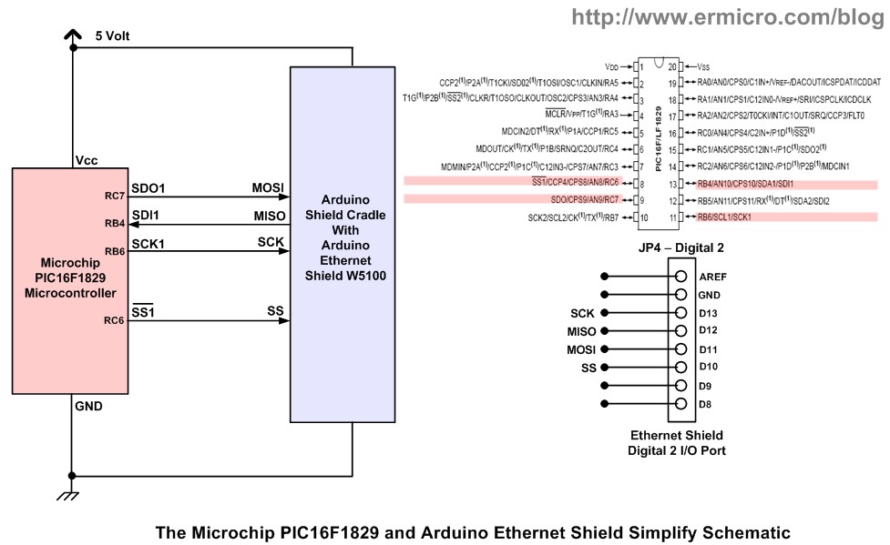
As good electronics hobbyists this “hick-up” will not prevent us to take advantage of this useful Arduino Shield stuff out there, therefore I used the Sparkfun Arduino ProtoShield board design and turn it into the Arduino Shield Cradle so we could use this Arduino shield with other development board as well. At the end of this tutorial I will present a simple Arduino Shield Cradle tester project using the standard Arduino EtherShield (with Wiznet W5100 chip) connected to PICJazz 20PIN board running Microchip PIC16F1829 microcontroller and run a simple ICMP (Internet Control Message Protocol) test over the Ethernet connection.
The Arduino Shield Cradle
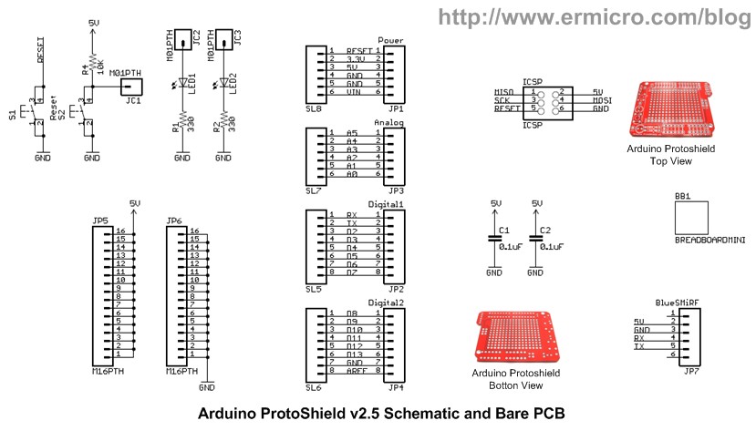
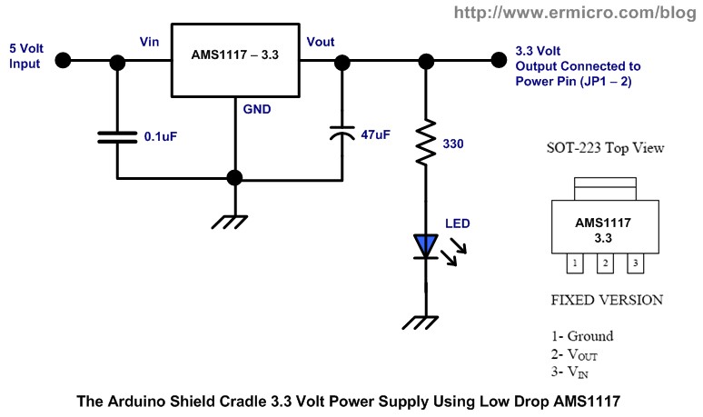
Instead of making our own Arduino Shield Cradle PCB design it is easier to make used of what is already available in the market, therefore I choose the Sparkfun Arduino ProtoShield Board v2.5 design and with just adding a few electronic parts we could have a nice Arduino Shield Cradle that could be used with any Arduino Shield hardware. This Arduino Shield Cradle also is equipped with a build-in 3.3 volt voltage regulator using Advanced Monolithic Systems AMS1117 low drop voltage regulator chip.
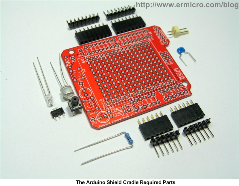
Now let’s list down all the necessary hardware and software needed to accomplished these projects:
1. One 330 Ohm Resistor
2. Capacitor: 0.1uF (1) and 47uF/16v (1)
3. Advanced Monolithic Systems AMS1117, 3.3 volt Low Drop Voltage Regulator
4. One 3 mm blue LED
5. One momentary reset push button
6. One 2 Pin Polarized Connector for power supply
7. Standard Arduino board female pin head connector (2 x 8-pin and 2 x 6-pin)
8. Bended male extension pin head connector (2 x 8-pin and 2 x 6-pin)
9. Sparkfun ProtoShield Board v2.5 design
10. PICJazz 20-PIN learning board from ermicro with Microchip 8-bit PIC16F1829 Microcontroller
11. Arduino Ethernet Shield W5100
12. Microchip PICKit3 programmer
13. Microchip MPLAB IDE version 8.63 and Microchip HI-TECH C Compiler for the PIC10/12/16 MCU family version 9.80
14. Reference Document: Microchip PIC16F1829 datasheet, Arduino Ethernet Shield W5100 datasheet, Wiznet W5100 datasheet, and Arduino Board datasheet.
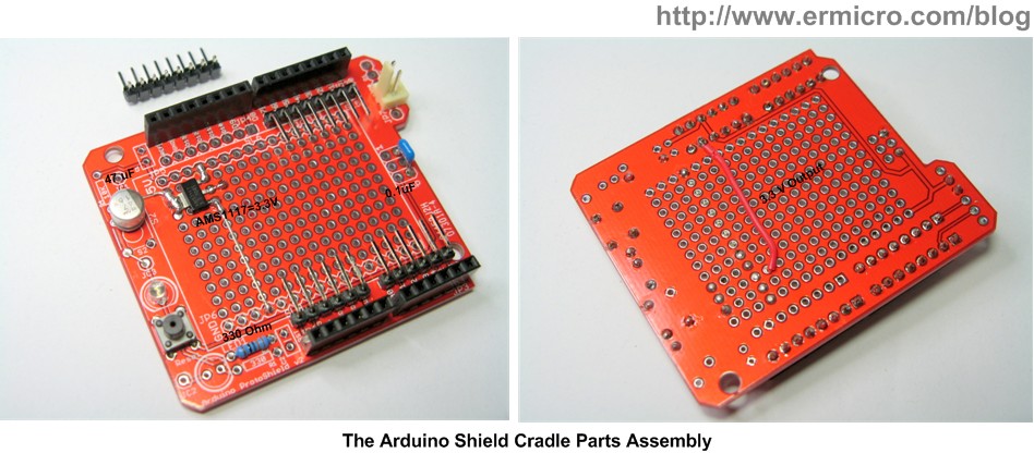
The following pictures show of how I constructed this Arduino Shield Cradle using the Sparkfun Arduino ProtoShield board design.
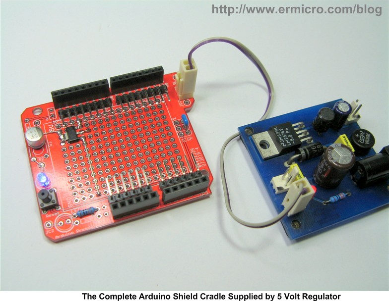
As you could see from the Arduino Shield Cradle assembly above, you only need a view jumper to connect all the required electronic parts because I make used of the available PCB design connection. For example I placed the 47 uF capacitor on the S2 switch; 0.1uF capacitor on ICSP connector; I make used of the Arduino ProtoShield board LED2 with R2 (330 Ohm) as the AMS1117 3.3 volt indicator and the BlueSMiRF connector for the Arduino Shield Cradle board 5 volt power terminal. At the bottom you only need one jumper to connect the AMS1117 Vout (3.3 volt) to pin 2 on the Arduino ProtoShield board JP1 (Power Pin). The following picture show the complete Arduino Shield Cradle tested with the 5 Volt voltage regulators.
Testing the Arduino Shield Cradle
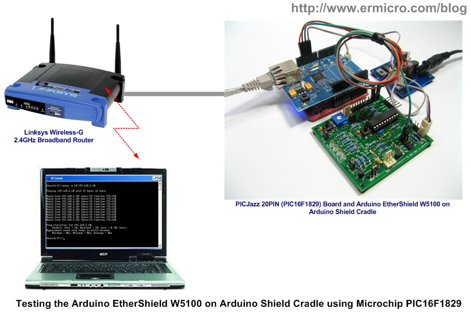
Of course this project is not complete without testing our Arduino Shield Cradle, therefore to make it more interesting I used the Arduino Ethernet Shield W5100 as our target hardware shield to test this Arduino Shiled Cradle. This time I used one of the Microchip 20 pin 8-bit newest and powerful midrange PIC16F1829 microcontroller with PICJazz 20PIN development board.
The Microchip PIC16F1829 microcontroller could be considered as the product that fills the gap between the PIC16F midrange and the PIC18F high-end series. It’s equipped with many peripherals that before only could be found on the PIC18F high-end series such as In-Circuit Debug (ICD) via Two Pins, Internal temperature Sensor, 5 Timers, Two Enhanced CCP (ECCP) Modules, Two Master Synchronous Serial Port (MSSP) with SPI (Serial Peripheral Interface) and I2C (read I square C), and mTouch Sensing Oscillator Module.
On this tutorial I will use the PIC16F1829 SPI peripheral to communicate with the Arduino Ethernet Shield W5100. Basically the Wiznet W5100 (used in standard Arduino Ethernet Shield) implements a full-featured of standard IEEE 802.3 (Ethernet physical and data link layer) and powerful TCP/IP stack inside the chip; this make the Wiznet W5100 chip is a nature choice for integrating the embedded system into the internet.
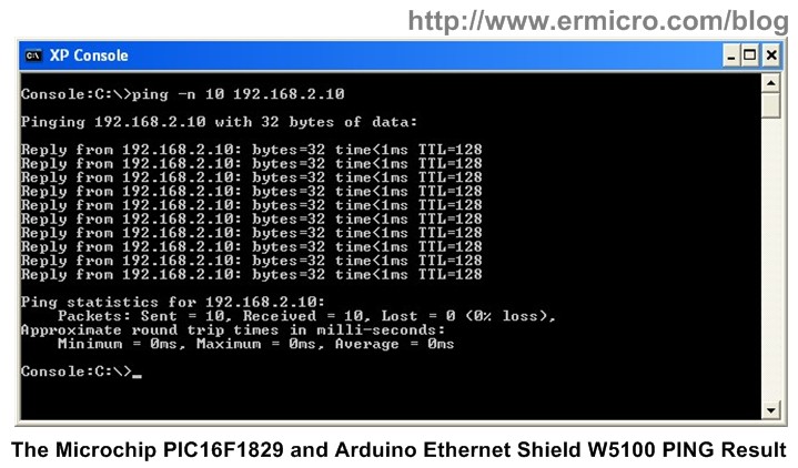
By initializing the Wiznet W5100 chip we will activate the build-in ICMP (Internet Control Message Protocol, documented in RFC 792) protocol server inside the chip, therefore we could easily test the W5100 chip by sending the “ping” command and receive “alive” response from it. The following is the complete C code for initializing the Arduino Ethernet Shield W5100:
/* **********************************************************************************
**  File Name    : picping.c
**  Version      : 1.0
**  Description  : Wiznet 5100 Arduino Shield Cradle Demo
**  Author       : RWB
**  Target       : PICJazz 20PIN with Microchip PIC16F1829 Microcontroller
**  Compiler     : Microchip HI-TECH C Compiler for the PIC10/12/16 MCU family V9.80
**  IDE          : Microchip MPLAB IDE v8.63
**  Programmer   : Microchip PICKit3 Firmware Suite Version 01.26.43
**  Last Updated : 28 May 2011
** ***********************************************************************************/
#include <pic.h>
#include <stdio.h>
#include <stdlib.h>
/*   PIC16F1829 Configuration Bit:
**   CONFIG1 Address 0x8007
**
**   FOSC_INTOSC - Internal OSC, I/O function on CLKIN pin
**   WDTE_OFF    - Wacthdog Timer Disable
**   PWRTE_ON    - Power Up Timer Enable
**   MCLRE_ON    - Master Clear Enable
**   CP_OFF      - Program memory code protection is disabled
**   CPD_OFF     - Data memory code protection is enabled
**   BOREN_ON    - Brown-out Reset Enable
**   IESO_OFF    - Internal/External Switchover mode is disabled
**   FCMEN_OFF   - Fail-Safe Clock Monitor is disabled
*/
__CONFIG(FOSC_INTOSC & WDTE_OFF & PWRTE_ON & MCLRE_ON & CP_OFF & CPD_OFF & BOREN_ON & IESO_OFF & FCMEN_OFF);
/*   PIC16F1829 Configuration Bit:
**   CONFIG2 Address 0x8008
**
**   WRT_OFF     - Write protection off
**   PLLEN_OFF   - 4x PLL Disabled
**   STVREN_ON   - Stack Overflow or Underflow will cause a Reset
**   BORV_19     - Brown-out Reset Voltage (VBOR) set to 1.9 V
**   LVP_ON      - Low-voltage programming enabled
**
*/
__CONFIG(WRT_OFF & PLLEN_OFF & STVREN_ON & BORV_19 & LVP_ON);
// Using Internal Clock of 8 MHz
#define FOSC 8000000L
// UART Baud Rate
#define BAUD_RATE 19200
// Wiznet W5100 Register Addresses
#define MR   0x0000   // Mode Register
#define GAR  0x0001   // Gateway Address: 0x0001 to 0x0004
#define SUBR 0x0005   // Subnet mask Address: 0x0005 to 0x0008
#define SAR  0x0009   // Source Hardware Address (MAC): 0x0009 to 0x000E
#define SIPR 0x000F   // Source IP Address: 0x000F to 0x0012
#define RMSR 0x001A   // RX Memory Size Register
#define TMSR 0x001B   // TX Memory Size Register
// Wiznet W5100 Op Code
#define WIZNET_WRITE_OPCODE 0xF0
#define WIZNET_READ_OPCODE 0x0F
// PIC16F1829 TIMER6 Based Delay Implementation Function
void _delay_ms(unsigned int ms)
{
  unsigned int i;
  // TIMER6 Period = PR6 x 4 x Tosc x Prescaller second
  // TIMER6 Period = 50 x 4 x 1/8000000 x 4 = 0.0001 second = 0.1 ms
  PR6=50;                           // Maximum Counter
  for (i=0; i <= (ms * 10);i++) {
    TMR6=0;                         // Reset TIMER6 Counter
    PIR3bits.TMR6IF=0;              // Clear TIMER6 Interrupt Flag
    T6CONbits.TMR6ON=1;             // Turn On TIMER6
    while(PIR3bits.TMR6IF != 1);    // Wait until TMR6 > PR6 (Overflow)
    T6CONbits.TMR6ON=0;             // Turn Off TIMER6
  }
}
void UARTInit(void)
{
  unsigned int BRGValue;
  TRISBbits.TRISB5 = 1;         // Set Port RB5 for UART RX (Input)
  TRISBbits.TRISB7 = 0;         // Set Port RB7 for UART TX (Output)
  // Baud Rate formula for SYNC=0 (Async), BRG16=0 (8-bit), BRGH=1 (High Speed)
  // 0.16% Error for 8 MHz Oscilator Clock. Actual Rate will be 19231.
  // BAUD_RATE = FOSC / (16 x (SPBRGL:SPBGRH + 1))
  BRGValue=(unsigned int) ((FOSC/BAUD_RATE)/16) - 1;
  SPBRGH=(BRGValue >> 8 ) & 0x00FF;
  SPBRGL=BRGValue;
  TXSTA = 0b00100100;  // Async, 8 bit, High Speed, and Enable Transmit (TXEN=1)
  RCSTA = 0b10010000;  // Serial Port Enable, Async,8-bit and Enable Receipt (CREN=1)
  BAUDCON=0b00000000;
}
void putch(unsigned char data)
{
  // Send Data when PIR1bits.TXIF bit is clear
  while(!PIR1bits.TXIF) continue;
  TXREG = data;
}
unsigned char getch(void) {
  // Get Data when PIR1bits.RCIF bit is clear
  while(!PIR1bits.RCIF) continue;
  return RCREG;
}
unsigned char getche(void)
{
  unsigned char c;
  putch(c = getch());
  return c;
}
void ansi_cl(void)
{
  // ANSI clear screen: cl=\E[H\E[J
  putchar(27);
  putchar('[');
  putchar('H');
  putchar(27);
  putchar('[');
  putchar('J');
}
void ansi_me(void)
{
  // ANSI turn off all attribute: me=\E[0m
  putchar(27);
  putchar('[');
  putchar('0');
  putchar('m');
}
void SPI_Write(unsigned int addr,unsigned char data)
{
  // Activate the CS pin
  PORTCbits.RC6 = 0;
  // Start Wiznet W5100 Write OpCode transmission
  SSP1BUF = WIZNET_WRITE_OPCODE;
  // Wait for transmission complete
  while(!SSP1STATbits.BF);
  // Start Wiznet W5100 Address High Bytes transmission
  SSP1BUF = (addr & 0xFF00) >> 8;
  // Wait for transmission complete
  while(!SSP1STATbits.BF);
  // Start Wiznet W5100 Address Low Bytes transmission
  SSP1BUF = addr & 0x00FF;
  // Wait for transmission complete
  while(!SSP1STATbits.BF);

  // Start Data transmission
  SSP1BUF = data;
  // Wait for transmission complete
  while(!SSP1STATbits.BF);
  // CS pin is not active
  PORTCbits.RC6 = 1;
}
unsigned char SPI_Read(unsigned int addr)
{
  // Activate the CS pin
  PORTCbits.RC6 = 0;
  // Start Wiznet W5100 Read OpCode transmission
  SSP1BUF = WIZNET_READ_OPCODE;
  // Wait for transmission complete
  while(!SSP1STATbits.BF);
  // Start Wiznet W5100 Address High Bytes transmission
  SSP1BUF = (addr & 0xFF00) >> 8;
  // Wait for transmission complete
  while(!SSP1STATbits.BF);
  // Start Wiznet W5100 Address Low Bytes transmission
  SSP1BUF = addr & 0x00FF;
  // Wait for transmission complete
  while(!SSP1STATbits.BF);

  // Send Dummy transmission for reading the data
  SSP1BUF = 0x00;
  // Wait for transmission complete
  while(!SSP1STATbits.BF);

  // CS pin is not active
  PORTCbits.RC6 = 1;
  return(SSP1BUF);
}
void W5100_Init(void)
{
  // Ethernet Setup
  unsigned char mac_addr[] = {0x00,0x16,0x36,0xDE,0x58,0xF6};
  unsigned char ip_addr[] = {192,168,2,10};
  unsigned char sub_mask[] = {255,255,255,0};
  unsigned char gtw_addr[] = {192,168,2,1};
  // Setting the Wiznet W5100 Mode Register: 0x0000
  SPI_Write(MR,0x80);            // MR = 0b10000000;
  _delay_ms(1);
  printf("Reading MR: %d\n\r\n\r",SPI_Read(MR));
  // Setting the Wiznet W5100 Gateway Address (GAR): 0x0001 to 0x0004
  printf("Setting Gateway Address %d.%d.%d.%d\n\r",gtw_addr[0],gtw_addr[1],\
          gtw_addr[2],gtw_addr[3]);
  SPI_Write(GAR + 0,gtw_addr[0]);
  SPI_Write(GAR + 1,gtw_addr[1]);
  SPI_Write(GAR + 2,gtw_addr[2]);
  SPI_Write(GAR + 3,gtw_addr[3]);
  _delay_ms(1);
  printf("Reading GAR: %d.%d.%d.%d\n\r\n\r",SPI_Read(GAR + 0),SPI_Read(GAR + 1),\
          SPI_Read(GAR + 2),SPI_Read(GAR + 3));
  // Setting the Wiznet W5100 Source Address Register (SAR): 0x0009 to 0x000E
  printf("Setting Source Address %.2x:%.2x:%.2x:%.2x:%.2x:%.2x\n\r",mac_addr[0],mac_addr[1],\
          mac_addr[2],mac_addr[3],mac_addr[4],mac_addr[5]);
  SPI_Write(SAR + 0,mac_addr[0]);
  SPI_Write(SAR + 1,mac_addr[1]);
  SPI_Write(SAR + 2,mac_addr[2]);
  SPI_Write(SAR + 3,mac_addr[3]);
  SPI_Write(SAR + 4,mac_addr[4]);
  SPI_Write(SAR + 5,mac_addr[5]);
  _delay_ms(1);
  printf("Reading SAR: %.2x:%.2x:%.2x:%.2x:%.2x:%.2x\n\r\n\r",SPI_Read(SAR + 0),SPI_Read(SAR + 1),\
          SPI_Read(SAR + 2),SPI_Read(SAR + 3),SPI_Read(SAR + 4),SPI_Read(SAR + 5));
  // Setting the Wiznet W5100 Sub Mask Address (SUBR): 0x0005 to 0x0008
  printf("Setting Sub Mask Address %d.%d.%d.%d\n\r",sub_mask[0],sub_mask[1],\
          sub_mask[2],sub_mask[3]);
  SPI_Write(SUBR + 0,sub_mask[0]);
  SPI_Write(SUBR + 1,sub_mask[1]);
  SPI_Write(SUBR + 2,sub_mask[2]);
  SPI_Write(SUBR + 3,sub_mask[3]);
  _delay_ms(1);
  printf("Reading SUBR: %d.%d.%d.%d\n\r\n\r",SPI_Read(SUBR + 0),SPI_Read(SUBR + 1),\
          SPI_Read(SUBR + 2),SPI_Read(SUBR + 3));
  // Setting the Wiznet W5100 IP Address (SIPR): 0x000F to 0x0012
  printf("Setting IP Address %d.%d.%d.%d\n\r",ip_addr[0],ip_addr[1],\
          ip_addr[2],ip_addr[3]);
  SPI_Write(SIPR + 0,ip_addr[0]);
  SPI_Write(SIPR + 1,ip_addr[1]);
  SPI_Write(SIPR + 2,ip_addr[2]);
  SPI_Write(SIPR + 3,ip_addr[3]);
  _delay_ms(1);
  printf("Reading SIPR: %d.%d.%d.%d\n\r\n\r",SPI_Read(SIPR + 0),SPI_Read(SIPR + 1),\
          SPI_Read(SIPR + 2),SPI_Read(SIPR + 3));

  // Setting the Wiznet W5100 RX and TX Memory Size, we use 2KB for Rx/Tx 4 channel
  printf("Setting Wiznet RMSR and TMSR\n\r\n\r");
  SPI_Write(RMSR,0x55);
  SPI_Write(TMSR,0x55);
  printf("Wiznet W5100 Initialized is Done!\n\r");
}
void main(void)
{
  OSCCON=0x70;         // Select 8 MHz internal clock

  // PIC16F1829 I/O Port Initialization
  PORTA = 0x00;        // Initial PORT A
  LATA  = 0x00;        // Clear PORT A
  TRISA = 0x03;        // Input for RA0 and RA1
  ANSELA = 0b00000001; // Set Port AN0 to analog input Others as digital I/O
  PORTB = 0x00;        // Initial PORT B
  LATB  = 0x00;        // Clear PORT B
  TRISB = 0x00;        // Set Port B as Output
  ANSELB = 0b00000000; // Set all as digital Output
  PORTC = 0x00;        // Initial PORT C
  LATC  = 0x00;        // Clear PORT C
  TRISC = 0x00;        // Set Port C as Output
  ANSELC = 0b00000000; // Set all as digital Output
  // TIMER6 Delay Initialization
  // TIMER6 Period = PR6 x 4 x Tosc x Prescaller second
  T6CON = 0b00000010;  // Used Prescaler 4
  // Initial the PIC16F1829 Ehanced UART
  UARTInit();
  // Initial the PIC16F1829 SPI Peripheral
  TRISCbits.TRISC6 = 0;   // RC6/SS - Output (Chip Select)
  TRISCbits.TRISC7 = 0;   // RC7/SDO - Output (Serial Data Out)
  TRISBbits.TRISB4 = 1;   // RB4/SDI - Input (Serial Data In)
  TRISBbits.TRISB6 = 0;   // RB6/SCK - Output (Clock)

  SSP1STAT = 0x40;        // Set SMP=0 and CKE=1
  SSP1CON = 0x20;         // Enable SSP1EN=1, SSP1M = 0000 - SPI Master with Fsosc/4
  PORTCbits.RC6 = 1;      // Disable Chip Select
  // Disabling the interrupts.
  INTCON=0;
  // Initial the Wiznet W5100
  ansi_me();
  ansi_cl();
  printf("PICJazz 20PIN - Microchip PIC16F1829 Microcontroller\n\r");
  printf("Arduino Ethernet W5100 Shield Cradle Initialized\n\r\n\r");
  W5100_Init();

  // Loop forever
  for(;;) {
  }
}
/* EOF: picping.c */
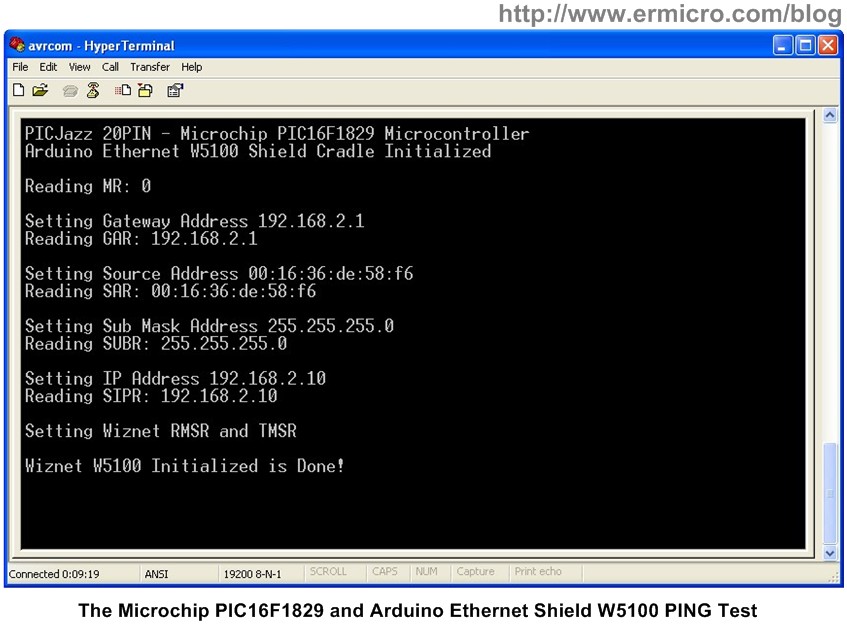
After compiling and downloading the HEX program into the PICJazz 20PIN board; connect the RJ45 connector UTP ethernet cable to your hubs/switch or you could connect directly with the cross configuration cable to your computer. Use the serial terminal such as Hyperterminal, puTTY or Tera Term and configure it to accept the serial connection with 19200 baud rate, 8-bit data with No Parity Check.
Now you are ready to test the Arduino Shield Ethernet W5100 by using the “ping” command as shown on these following pictures:
You could read detail information of how to use the Wiznet W5100 chip on “Integrating Wiznet W5100, WIZ811MJ network module with Atmel AVR Microcontroller” and using Microchip PIC microcontroller SPI (Serial Peripheral Interface) on “Using Serial Peripheral Interface (SPI) with Microchip PIC18 Families Microcontroller” articles.
Now it’s time to watch the Arduino Shield Cradle assembly and testing process on this following video:
The Final Thought
One of the Arduino framework successful stories is come from the various well designs Arduino Shield hardware available on the market, which could bring broader range of various embedded application that could be applied with the Arduino board. Now with the Arduino Shield Cradle in your hand you could easily use these various shields on any development board or microcontroller type in your next embedded application project.
Bookmarks and Share


