Blog Entry
Working with Atmel AVR Microcontroller Basic Pulse Width Modulation (PWM) Peripheral
April 30, 2011 by rwb, under Microcontroller.
Pulse Width Modulation (PWM) is a technique widely used in modern switching circuit to control the amount of power given to the electrical device. This method simply switches ON and OFF the power supplied to the electrical device rapidly. The average amount of energy received by the electrical device is corresponding to the ON and OFF period (duty cycle); therefore by varying the ON period i.e. longer or shorter, we could easily control the amount of energy received by the electrical device. The Light Emitting Diode (LED) will respond to this pulse by dimming or brighten its light while the electrical motor will respond to this pulse by turning its rotor slow or fast.
The above picture show a typical Pulse Width Modulation (PWM), the PWM duty cycle is the proportion of the signal “ON” time to one period (T) of the signal time. The duty cycle will be higher when the ON time is longer than the OFF time and vice versa. Duty cycle is expressed in percentage; therefore you could define the duty cycle of PWM signal as follow:
The 100% PWM duty cycle means it’s fully ON and we could say that 100% of the power or energy is delivered to the electrical device, while 15% duty cycle means only 15% of the power is being delivered to the electrical device. This average in power could be presented as average in voltage as follow:
The PWM signal normally has a fixed frequency (period) with a duty cycle that could vary from 0% to 100%. Now you understand that by just adjusting the PWM duty cycle we could easily control the LED brightness or the electrical motor spinning speed.
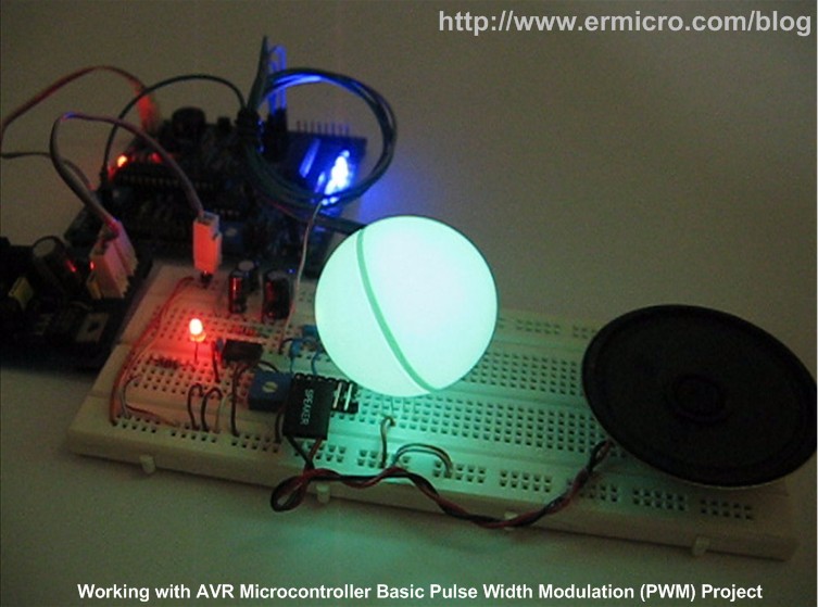
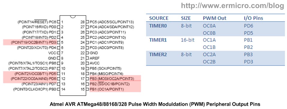
Today most of modern microcontroller has a build in PWM peripheral inside; this make generating PWM signal is become easy and straightforward, you could read more about non microcontroller PWM base generator on “The LM324 Quad Op-Amp Line Follower Robot with Pulse Width Modulation” article on this blog. On this tutorial we are going to use Atmel AVR ATMega168 microcontroller which support up to 6 PWM output simultaneously and at the end of this tutorial we will take advantage of all the available PWM peripheral to make a nice RGB LED Light and Sound Show.
The AVR Microcontroller PWM Peripheral
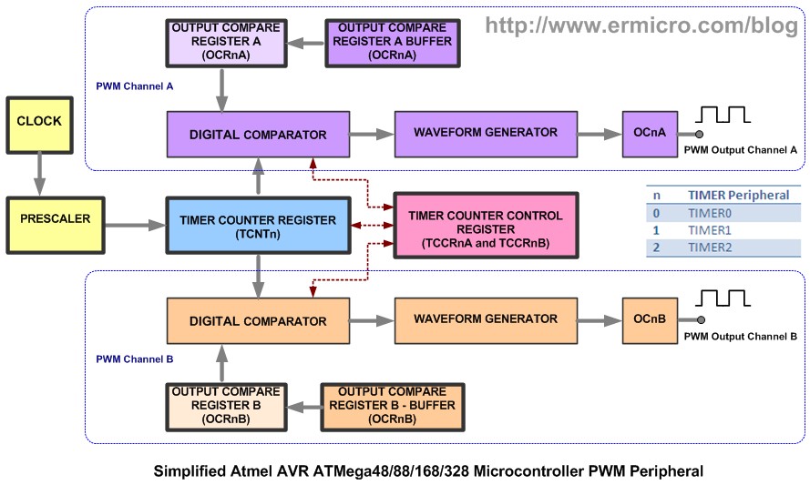
Most of the microcontroller PWM peripheral depends on the TIMER peripheral to provide the PWM signals frequency. The PWM peripheral will use the TIMER counter register (TCNT) as a digital step-up /down and continuously compare to the pre-determine duty cycle register (OCR – output compare register) value.
When TCNT equal to OCR value the wave generator circuit will set (ON) or reset (OFF) the corresponding microcontroller PWM I/O ports. The following picture show a simplified version of Atmel AVR ATMega168 microcontroller PWM peripheral (please refer to the Atmel ATMega48/88/168/328 datasheet for more information):
Each of the AVR ATMega168 microcontrollers TIMER has two PWM channels named channel A and channel B, where each channel has its own output compare register (OCR). From the diagram above you could see that both channel share the same TIMER counter register (TCNT), this mean you could only have one PWM frequency for each TIMER (TIMER0, TIMER1, and TIMER2) but you could have different duty cycle on each channel (A and B). The AVR ATMega48/88/168/328 microcontroller provides three PWM modes which are Fast PWM Mode, Phase Correct PWM Mode, and Phase and Frequency Correct Mode. The last mode is only available on TIMER1 (16-bit timer). Ok before we continue let’s list down the hardware and software needed for this tutorial:
1. AVRJazz Mega168 or AVRJazz Ultimate 28P board (I used in this project), you could also use any AVR ATMega168 board or bare ATMega168, whatever available to you (the electronics components listed here is just for the final project)
2. One Bread board
3. Resistors: 10K (1), 15K (1), and 18 (1)
4. One 10K Trimpot
5. Non polar Capacitor 0.1uF (3) and 0.01uF (1)
6. Polar Capacitor 220uF/16V (1) and 10uF/16V (1)
7. One 5 mm RGB LED
8. National Semiconductor LM386 IC
9. One white ping-pong ball for defusing the RGB LED light
10. One Speaker
11. The latest Atmel AVRStudio (in this project I used v4.18) and WinAVR GNU-C Compiler (in this project I used WinAVR 20100110)
12. AVR Microcontroller Programmer
13. Atmel ATMega48/88/168/328 and LM386 datasheet.
The AVR Fast PWM Mode
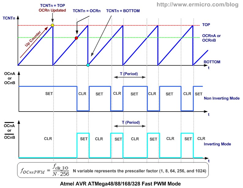
The AVR fast PWM mode could generate the most high frequency PWM waveform compared to the other two PWM modes (i.e. Phase Correct or Phase and Frequency Correct mode). This PWM mode simply uses the TIMER counter register (TCNTn, where n represent the TIMER 0, TIMER1, and TIMER2 respectively) incremental value which is start from 0x00 (BOTTOM) to 0xFF (8-bit TOP) or 0xFFFF (16-bit TOP).
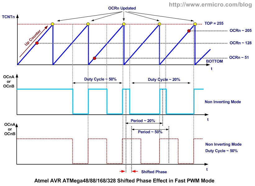
When the TIMER counter register reach the output compare register (OCRnA or OCRnB) value then the wave generator circuit will CLEAR (logical low) the output compare bit channel (OCnA or OCnB). When the TIMER counter register value reach the TOP value then it will SET (logical high) the output compare bit channel and the whole process will repeat again from BOTTOM. This PWM generation process could be shown on this following diagram:
As shown on the diagram above, the behavior of output compare bit channel (OCnA or OCnB) output could be set to non-inverting (CLEAR and SET) or inverting (SET and CLEAR) mode by setting the compare match channel bit (COMnA1, COMnA0, COMnB1, and COMnB0) on Timer/Counter register A (TCCRnA). The Fast PWM mode could be set by setting the wave generation mode bit (WGM01 and WGM00) on Timer/Counter register A (TCCRnA) and WGM02 bit on TCCRnB register. When the TIMER counter register (TCNTn) equal to Output Compare Register (OCRnA or OCRnB) it will generate the Output Compare interrupt and when the TCNTn register reach TOP it will generate the TIMER overflow interrupt (TOV).
As you see at the Atmel AVR microcontroller PWM peripheral diagram above when we update the Output Compare Register (OCRnA and OCRnB) value, the value will be updated on the Output Compare Register Buffer first and when the TIMER0 Counter Register (TCNT0) reach TOP then the OCRn register will be updated with the OCRn buffer value and at the same time the Output Compare Bits (OCnA or OCnB) will be set.
On this following C code, we are going to use TIMER0 Fast PWM mode on both channel A and channel B.
//***************************************************************************
//  File Name	 : avrpwm01.c
//  Version	 : 1.0
//  Description  : AVR TIMER0 Fast PWM Mode
//  Author       : RWB
//  Target       : AVRJazz Ultimate 28PIN Board
//  Compiler     : AVR-GCC 4.3.3; avr-libc 1.6.7 (WinAVR 20100110)
//  IDE          : Atmel AVR Studio 4.18
//  Programmer   : AVRJazz Mega168 STK500 v2.0 Bootloader
//               : AVR Visual Studio 4.18, STK500 programmer
//  Last Updated : 21 March 2011
//***************************************************************************
#include <avr/io.h>
#include <util/delay.h>
int main(void)
{
  unsigned char duty_cyc_a,duty_cyc_b;
  // Initial PORT Used
  DDRD = 0b11111111;     // Set PORTD: Output
  PORTD = 0x00;
  // Initial TIMER0 Fast PWM
  // Fast PWM Frequency = fclk / (N * 256), Where N is the Prescaler
  // f_PWM = 11059200 / (64 * 256) = 675 Hz
  TCCR0A = 0b10100011; // Fast PWM 8 Bit, Clear OCA0/OCB0 on Compare Match, Set on TOP
  TCCR0B = 0b00000011; // Used 64 Prescaler
  TCNT0 = 0;           // Reset TCNT0
  OCR0A = 0;           // Initial the Output Compare register A & B
  OCR0B = 0;
  duty_cyc_a=0;	// Initial Duty Cycle for Channel A
  duty_cyc_b=255;	// Initial Duty Cycle for Channel B

  for(;;) {            // Loop Forever
    while(duty_cyc_a < 255) {
      OCR0A=duty_cyc_a++;
      OCR0B=duty_cyc_b--;
       _delay_ms(10);
    }

    while(duty_cyc_b < 255) {
      OCR0A=duty_cyc_a--;
      OCR0B=duty_cyc_b++;
      _delay_ms(10);
    }
  }

  return 0;	        // Standard Return Code
}
/* EOF: avrpwm01.c */
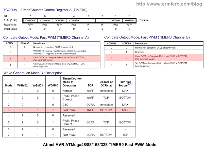
The TIMER0 Fast PWM mode is activated by setting the Wave Generation Mode bits WGM02=0, WGM01=1, and WGM00 = 1 on TIMER0 Timer/Counter control Registers (TCCR0A and TCCR0B) as follow:
// Initial TIMER0 Fast PWM
// Fast PWM Frequency = fclk / (N * 256), Where N is the Prescaler
// f_PWM = 11059200 / (64 * 256) = 675 Hz
TCCR0A = 0b10100011; // Fast PWM 8 Bit, Clear OCA0/OCB0 on Compare Match, Set on TOP
TCCR0B = 0b00000011; // Used 64 Prescaler
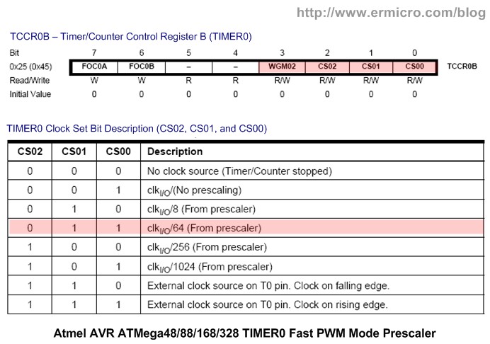
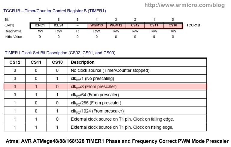
Therefore by assigning the Clock Set Bit CS02 = 0, CS01 = 1, and CS00 = 1 respectively, we tell the TIMER0 to use 64 as a prescaler, therefore you could calculate the PWM frequency if we use 11059200 Hz external crystal as follow:
PWM Frequency = Freq Clock / (prescaler x 256) = 11059200 / (64 x 256) = 675 Hz
You could freely choose or experiment with any PWM frequency that work best with the electrical devices that you want to control with the Fast PWM mode signal.
One of disadvantage using the Fast PWM mode to generate the PWM signal is the PWM phase is shifted when we change the PWM duty cycle. This because when the TIMER0 Counter Register (TCNTn) reach TOP and start from BOTTOM it will always SET (or CLEAR) the Output Compare Bits (OCnA or OCnB) despite the Output Compare Register (OCRnA and OCRnB) value; therefore when we change the duty cycle in Fast PWM mode the PWM signal phase is always shifted as illustrated on this following diagram:
This make the Fast PWM mode is not suitable when we want to use for controlling the motor speed precisely; therefore on our next discussion we will correct this shifted phase effect by using the AVR microcontroller Phase Correct PWM mode for generating the PWM signal.
Now as you understand of how to use the Fast PWM mode on TIMER0, you could easily adapt this principal to TIMER1 (16-bit) and TIMER2 (8-bit). Please refer to the Atmel ATMega48/88/168/328 datasheet for complete information.
The AVR Phase Correct PWM Mode
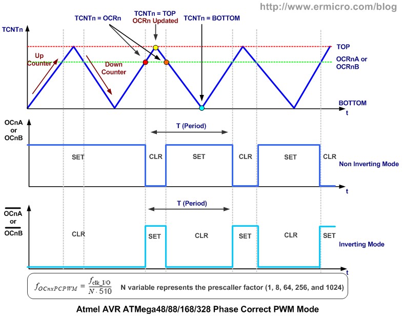
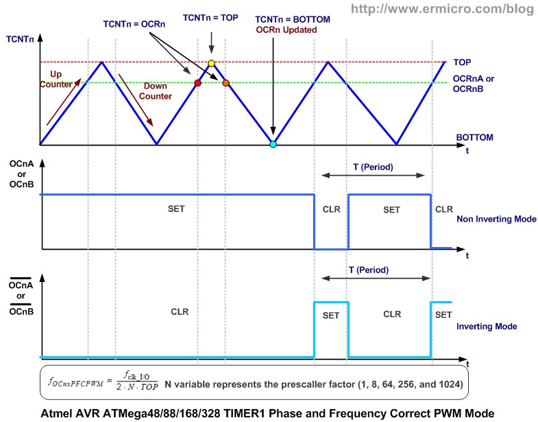
Differ from the Fast PWM Mode, the Phase Correct PWM mode is using dual slope TIMER counter. Basically the TIMER counter register (TCNTn) will increase its value (up counter) from BOTTOM to TOP and then decrease its value (down counter) from TOP to BOTTOM. When the TIMER counter register equal to the Output Compare Register (OCRnA and OCRnB) then the wave generator bit will simply toggle the Output Compare channel (OCnA and OCnB) as shown on this following diagram:
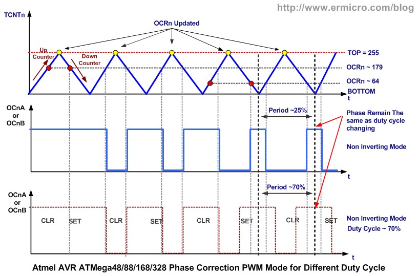
As shown on the diagram above you could see that the Phase Correct PWM mode will have half of the PWM signal frequency compared to the fast PWM mode. Because of the dual slope technique used in the Phase Correct PWM mode to generate the PWM signal, therefore the phase correct PWM mode is more precision and suitable to be used as a motor controller, because as we change the PWM signal duty cycle the phase between each duty cycles remain the same as illustrated on this following diagram:
On this following C code, we are going to use TIMER0 Phase Correct PWM mode on both channel A and channel B.
//***************************************************************************
//  File Name	 : avrpwm02.c
//  Version	 : 1.0
//  Description  : AVR TIMER0 Phase Correct PWM Mode
//  Author       : RWB
//  Target       : AVRJazz Ultimate 28PIN Board
//  Compiler     : AVR-GCC 4.3.3; avr-libc 1.6.7 (WinAVR 20100110)
//  IDE          : Atmel AVR Studio 4.18
//  Programmer   : AVRJazz Mega168 STK500 v2.0 Bootloader
//               : AVR Visual Studio 4.18, STK500 programmer
//  Last Updated : 21 March 2011
//***************************************************************************
#include <avr/io.h>
#include <util/delay.h>
int main(void)
{
  unsigned char duty_cyc_a,duty_cyc_b;
  // Initial PORT Used
  DDRD = 0b11111111;     // Set PORTD: Output
  PORTD = 0x00;
  // Initial TIMER0 Phase Correct PWM
  // Fast PWM Frequency = fclk / (N * 510), Where N is the Prescaler
  // f_PWM = 11059200 / (64 * 510) = 338.82 Hz
  TCCR0A = 0b10100001; // Phase Correct PWM 8 Bit, Clear OCA0/OCB0 on Compare Match, Set on TOP
  TCCR0B = 0b00000011; // Used 64 Prescaler
  TCNT0 = 0;           // Reset TCNT0
  OCR0A = 0;           // Initial the Output Compare register A & B
  OCR0B = 0;
  duty_cyc_a=0;		   // Initial Duty Cycle for Channel A
  duty_cyc_b=255;	   // Initial Duty Cycle for Channel B

  for(;;) {            // Loop Forever
	while(duty_cyc_a < 255) {
	  OCR0A=duty_cyc_a++;
	  OCR0B=duty_cyc_b--;
	  _delay_ms(10);
	}

	while(duty_cyc_b < 255) {
	  OCR0A=duty_cyc_a--;
	  OCR0B=duty_cyc_b++;
	  _delay_ms(10);
	}
  }

  return 0;	           // Standard Return Code
}
/* EOF: avrpwm02.c */
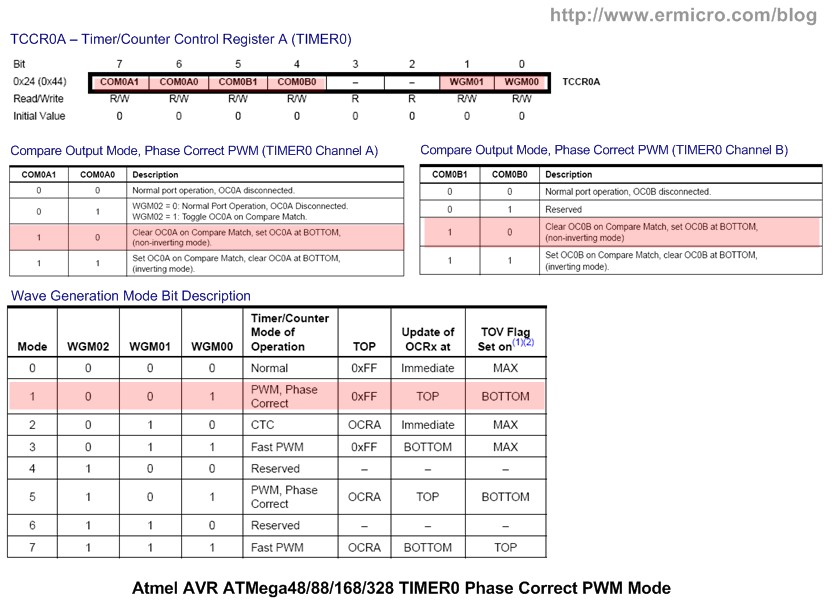
The TIMER0 Phase Correct PWM mode is activated by setting the Wave Generation Mode bits WGM02=0, WGM01=0, and WGM00 = 1 on TIMER0 Timer/Counter control Registers (TCCR0A and TCCR0B) as follow:
// Initial TIMER0 Phase Correct PWM
// Fast PWM Frequency = fclk / (N * 510), Where N is the Prescaler
// f_PWM = 11059200 / (64 * 510) = 338.82 Hz
TCCR0A = 0b10100001; // Phase Correct PWM 8 Bit, Clear OCA0/OCB0 on Compare Match, Set on TOP
TCCR0B = 0b00000011; // Used 64 Prescaler
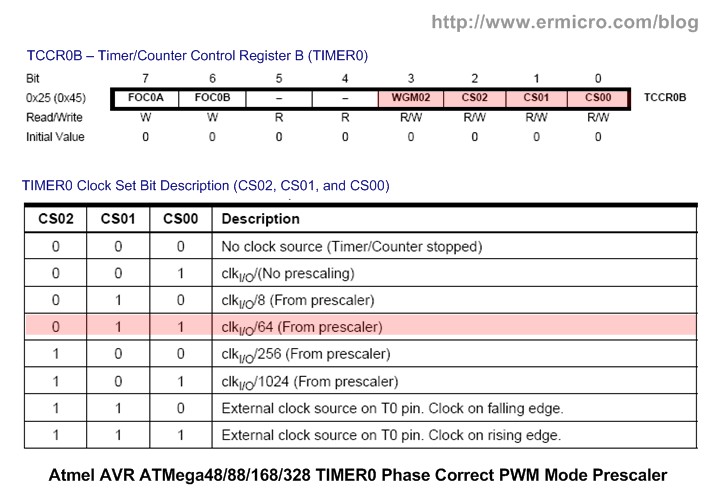
Therefore by assigning the Clock Set Bit CS02 = 0, CS01 = 1, and CS00 = 1 respectively, we tell the TIMER0 to use 64 as a prescaler, therefore the Phase Correct PWM frequency could be calculated as follow:
PWM Frequency = Freq Clock / (prescaler x 510) = 11059200 / (64 x 510) = 338.82 Hz
Again you could easily adapt this principal to TIMER1 (16-bit) and TIMER2 (8-bit) as well (please refer to Atmel ATMega48/88/168/328 datasheet for complete information).
The AVR Phase and Frequency Correct PWM Mode
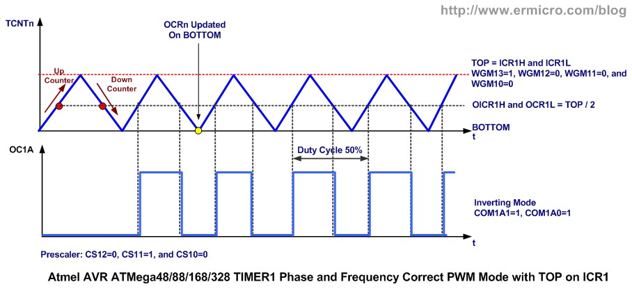
The Phase and Frequency Correct PWM Mode feature is only available on TIMER1 (16-bit). Basically the Phase and Frequency Correct PWM mode use the same dual slope technique used in Phase Correct PWM mode to generate the PWM signal. These two modes actually are identical if we never change the PWM signal frequency, but if we need to change the PWM signal frequency on fly, then we need to use the AVR ATMega168 microcontroller Phase and Frequency Correct mode to generate the PWM signal.
Differ from the Phase Correct PWM Mode, in Phase and Frequency Correct PWM Mode the Output Compare Register (OCRnA and OCRnB) is updated from the buffer when the Timer Counter Register (TCNTn) reaches BOTTOM instead of TOP in Phase Correct PWM Mode. The frequency could be change by changing the TOP value, here you could understand why we need to use the Phase and Frequency Correct PWM mode, because as we change the frequency and at the same time the PWM peripheral update the Output Compare register (OCRnA and OCRnB) then there will be a glitch in the PWM frequency signal.
In Phase and Frequency Correct PWM mode because the Output Compare Register is updated at the BOTTON therefore the rising and falling length of the PWM signal is always equal this result in frequency being corrected when we change the frequency on fly.
Typically in controlling the electrical device with PWM signal we seldom change the PWM frequency on fly, therefore the common application for this mode is to generate the sound. On this following C code example I used the Phase and Frequency Correct PWM to generated tone. Another example of using this PWM mode could be read in “AVR Twinkle-Twinkle Song Using PWM Project” article on this blog.
//***************************************************************************
//  File Name	 : avrpwm03.c
//  Version	 : 1.0
//  Description  : AVR TIMER0 Phase and Frequency Correct PWM Mode
//  Author       : RWB
//  Target       : AVRJazz Ultimate 28PIN Board
//  Compiler     : AVR-GCC 4.3.3; avr-libc 1.6.7 (WinAVR 20100110)
//  IDE          : Atmel AVR Studio 4.18
//  Programmer   : AVRJazz Mega168 STK500 v2.0 Bootloader
//               : AVR Visual Studio 4.18, STK500 programmer
//  Last Updated : 21 March 2011
//***************************************************************************
#include <avr/io.h>
#include <util/delay.h>
// Notes Frequency from http://www.phy.mtu.edu/~suits/notefreqs.html
// The Original frequency value (decimal) is converted to the integer value
#define C4  262
#define Cc4 277
#define D4  294
#define Dc4 311
#define E4  330
#define F4  349
#define Fc4 370
#define G4  392
#define Gc4 415
#define A4  440
#define Ac4 466
#define B4  494

#define C5  523
#define Cc5 554
#define D5  587
#define Dc5 622
#define E5  659
#define F5  698
#define Fc5 740
#define G5  783
#define Gc5 831
#define A5  880
#define Ac5 932
#define B5  988
#define C6 1047
// LED Display variables
unsigned char ledstat,led_out;
// PlayNotes function
void PlayNotes(unsigned int note_frequency,unsigned int duration)
{
   unsigned int top_value,duty_cycle;
   // Calculate the Top Value
   // TOP = Board Clock Frequency / (2 x N x Notes Frequency)
   // Where N is Prescler: 8
   topvalue=(F_CPU / (16 * note_frequency));
   // Reset the TIMER1 16 bit Counter
   TCNT1H = 0;
   TCNT1L = 0;

   // Set the TIMER1 Counter TOP value on ICR1H and ICR1L
   ICR1H = (top_value >> 8 ) & 0x00FF;
   ICR1L = top_value;

   // Set the TIMER1 PWM Duty Cycle on OCR1AH and OCR1AL
   // Always use half of the TOP value (PWM Ducty Cycle ~ 50%)
   duty_cycle=top_value / 2;
   OCR1AH=(duty_cycle >> 8 ) & 0x00FF;
   OCR1AL=duty_cycle;
   // Turn ON the TIMER1 Prescaler of 8
   TCCR1B |= (1<<CS11);

   // Notes Delay Duration
   _delay_ms(duration);

   // Turn OFF the TIMER1 Prescaler of 8
   TCCR1B &= ~(1<<CS11);
   // Delay Between Each Notes 1/5 duration
   _delay_ms(duration * 1/5);
}
// Display LED function
void DisplayLED(void)
{
  if (ledstat) {
    PORTD=led_out;
    led_out=led_out << 1;
    if (led_out >= 0x80) ledstat=0;
  } else {
    PORTD=led_out;
    led_out=led_out >> 1;
    if (led_out <= 0x01) ledstat=1;
  }
}
int main(void)
{
  unsigned int notes[25]={C4,Cc4,D4,Dc4,E4,F4,Fc4,G4,Gc4,A4,Ac4,B4,
                          C5,Cc5,D5,Dc5,E5,F5,Fc5,G5,Gc5,A5,Ac5,B5,C6};
  int icount;
  unsigned char pstat;
  unsigned int idelay;
  // Initial PORT Used
  DDRD = 0b11111111;   // Set PORTD as Output
  PORTD = 0b00000000;
  DDRB = 0b11111110;   // Set PB0 as Input and other as Output
  PORTB = 0b00000000;
  // Initial the ADC Peripheral
  ADCSRA = (1<<ADEN) | (1<<ADPS2) | (1<<ADPS1);
  // Use Free running Mode
  ADCSRB = 0b00000000;
  // Disable digital input on Channel 0
  DIDR0 = 0b00000001;
  // Initial TIMER1 Phase and Frequency Correct PWM
  // Set the Timer/Counter Control Register
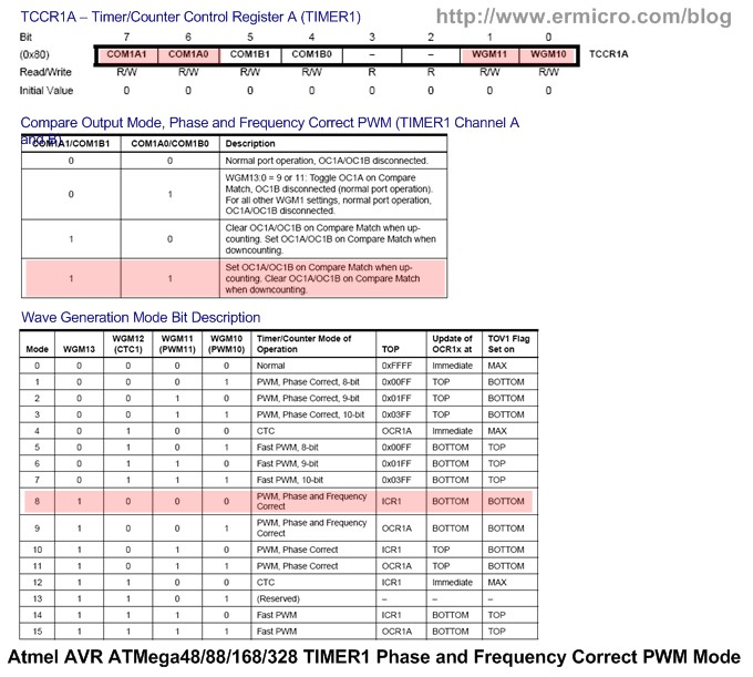
  TCCR1A = 0b11000000; // Set OC1A when up counting, Clear when down counting
  TCCR1B = 0b00010000; // Phase/Freq-correct PWM, top value = ICR1, Prescaler: Off

  // Initial Variables
  icount=0;
  pstat=1;
  led_out=1;
  ledstat=1;
  for(;;) {            // Loop Forever
    // Reading User Trimpot on Analog Channel 0
   ADMUX=0;
   // Start conversion by setting ADSC on ADCSRA Register
   ADCSRA |= (1<<ADSC);
   // wait until convertion complete ADSC=0 -> Complete
   while (ADCSRA & (1<<ADSC));
   // Get the ADC Result
   idelay=ADCW;
    DisplayLED();
    if (pstat) {
	  PlayNotes(notes[icount++],idelay);
	  if (icount > 24) {
		icount=24;
		pstat=0;
      }
    } else {
	  PlayNotes(notes[icount--],idelay);
	  if (icount < 0) {
		icount=0;
		pstat=1;
      }
    }
  }

  return 0;	           // Standard Return Code
}
/* EOF: avrpwm03.c */
To generate a controllable tone, we need to produce the exact frequency on each notes, the notes frequency could be found at this website address http://www.phy.mtu.edu/~suits/notefreqs.html. In order to generate the C5 note we have to produce the PWM frequency of 523.23 Hz at 50% duty cycle. Therefore by setting the Wave Generation Mode Bits WGM13=1, WGM12=0, WGM11=0, and WGM10=0 respectively, we choose the TIMER1 Phase and Frequency Correct PWM mode which has TOP value set on TIMER1 Input Capture Registers ICR1H and ICR1L; the Pulse Width is set on TIMER1 Output Compare Registers OCR1A and OCR1B.
With the precaler being set to 8 and board frequency of 1109200 Hz, we could easily calculate the TOP value of theC5 note as follow:
PWM Frequency = Freq Clock / (2 x N x TOP) = Freq Clock / (16 x TOP)
Or
TOP = Freq Clock / (16 x PWM Frequency) = 11059200 / (16 x 523) = 1322
Now by assigning the TOP value to the Input Capture Registers (ICR1H and ICR1L) and half of the TOP value to the Output Compare Register (OCR1AH and OCR1AL) we could produce the C5 notes with 50% duty cycle as shown on this following C code:
// Calculate the Top Value
// TOP = Board Clock Frequency / (2 x N x Notes Frequency)
// Where N is Prescler: 8
topvalue=(F_CPU / (16 * note_frequency));
// Set the TIMER1 Counter TOP value on ICR1H and ICR1L
ICR1H = (top_value >> 8 ) & 0x00FF;
ICR1L = top_value;
// Set the TIMER1 PWM Duty Cycle on OCR1AH and OCR1AL
// Always use half of the TOP value (PWM Ducty Cycle ~ 50%)
duty_cycle=top_value / 2;
OCR1AH=(duty_cycle >> 8 ) & 0x00FF;
OCR1AL=duty_cycle;
Because the ICR1H and ICR1L are the 8-bit registers, therefore we use the C language shift right operator to assign the upper 8-bit top_value to ICR1H and the lower 8-bit TOP value to ICR1L. We use similar principal to both OCR1H and OCR1L for the PWM duty cycle value (duty_cycle). The complete C code is implemented in PlayNotes() function, which accept the frequency and duration parameters to produce the needed sound. The AVR ATMega168 microcontroller ADC peripheral is used to control the playing notes delay by passing the trimpot voltage reading connected to ADC channel 0 (PC0), we could control the notes duration as shown on this following C code:
// Reading User Trimpot on Analog Channel 0
ADMUX=0;
// Start conversion by setting ADSC on ADCSRA Register
ADCSRA |= (1<<ADSC);
// wait until convertion complete ADSC=0 -> Complete
while (ADCSRA & (1<<ADSC));
// Get the ADC Result
idelay=ADCW;
...
...
PlayNotes(notes[icount++],idelay);
For more information about using Atmel AVR microcontroller ADC peripheral you could read “Analog to Digital Converter AVR C Programming” articles on this blog
The RGB LED Light and Sound Show
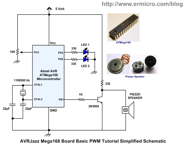
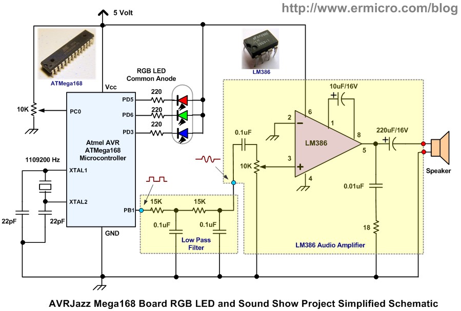
On this last tutorial we will put all together the AVR ATMega168 basic PWM lessons that we’ve learned and making some interesting RGB LED and Sound show as shown on this following schematic:
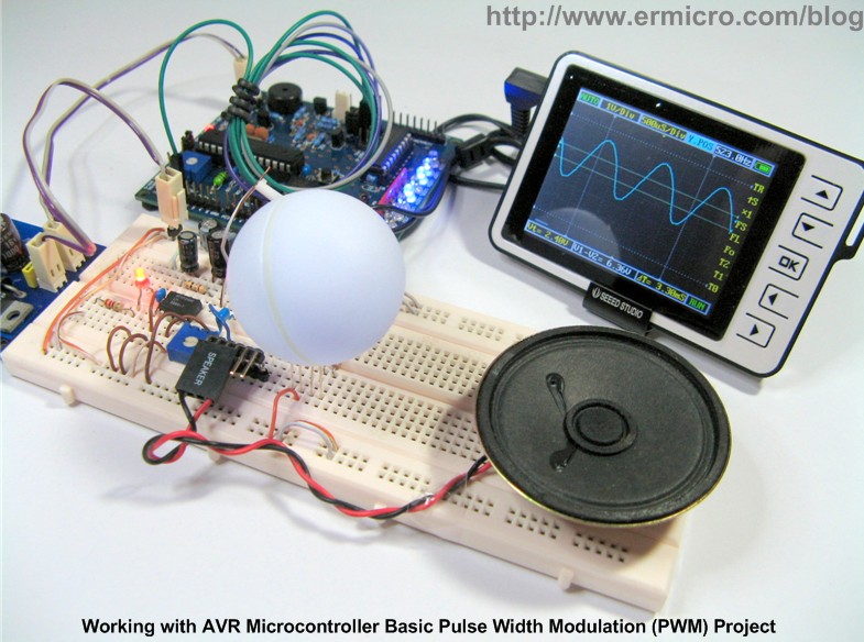
This RGB light and Sound show project used the well known LM386 linear amplifier IC from National Semiconductor which recently has been acquired by Texas Instrument (April 2011) to produce a quite loud sound from the TIMER1 Phase and Correct Frequency PWM mode through the speaker. The TIMER1 Output Compare Channel A (PB1) PWM signal is being passed through the passive low pass filter (is also called an integrator circuit for a non sinusoidal input signal such as square wave and triangle wave) in order to shape the square wave forms to become the sinusoidal wave forms before being amplified by the LM386 IC.
To make the low pass filter (LPF) become a good integrator circuit we have to choose the LPF cutoff frequency much less than the lowest frequency produced by the PWM signal but at the same time still produce an adequate signal level to drive the LM386 amplifier input. The cutoff frequency of LPF could be calculated as this following formula:
Frequency = 1 / (2 x pi x RC), where pi = 3.14159, R is resistance in Ohm, and C is capacitance in Farad
The lowest frequency produce by PWM signal is 262 Hz (C4 note), therefore by choosing R = 15K and C = 0.1uF, we could calculate the LPF cutoff frequency as follow:
Frequency = 1 / (2 x 3.14159 x 15000 x 0.0000001) = 106.10 Hz
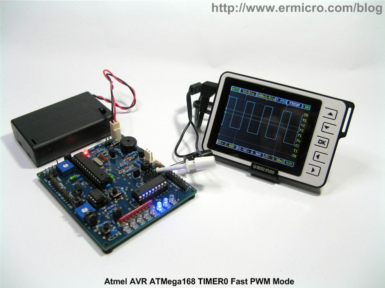
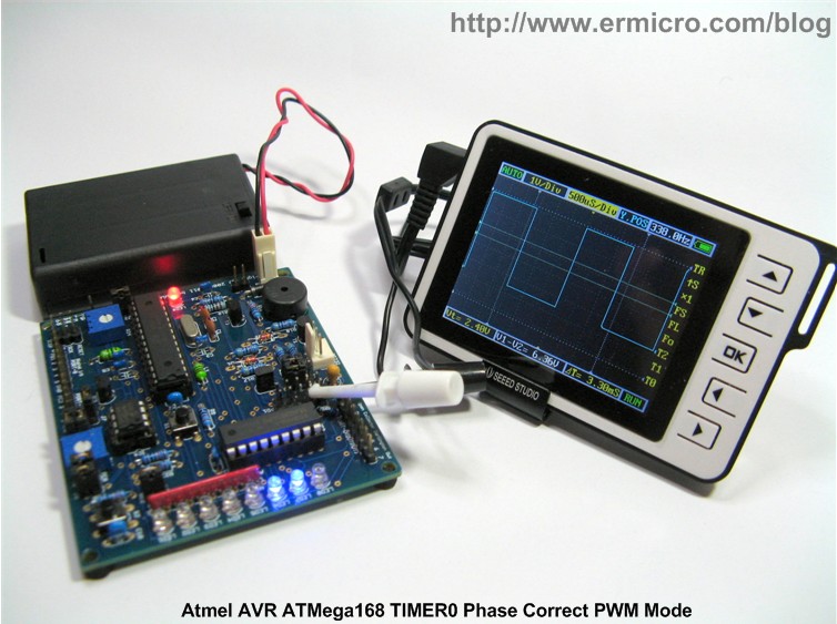
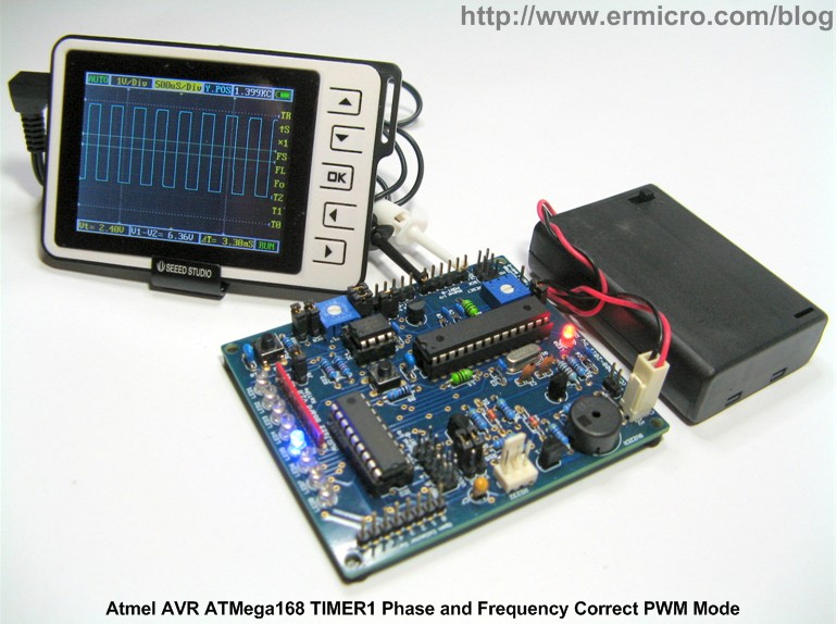
This method is used to ensure that we could get a quite nice sound produced on the speaker instead of just using raw square wave signal as shown on this following oscilloscope picture:
Each of the RGB LED cathodes is driven by TIMER0 Fast PWM channel A, channel B, and TIMER2 Phase Correct PWM channel B respectively. The following is the complete C code for our RGB LED Light and Sound Show final project:
//***************************************************************************
//  File Name	 : avrpwm04.c
//  Version	 : 1.0
//  Description  : AVR TIMER0 Phase and Frequency Correct PWM Mode
//  Author       : RWB
//  Target       : AVRJazz Ultimate 28PIN Board
//  Compiler     : AVR-GCC 4.3.3; avr-libc 1.6.7 (WinAVR 20100110)
//  IDE          : Atmel AVR Studio 4.18
//  Programmer   : AVRJazz Mega168 STK500 v2.0 Bootloader
//               : AVR Visual Studio 4.18, STK500 programmer
//  Last Updated : 22 March 2011
//***************************************************************************
#include <avr/io.h>
#include <util/delay.h>
#include <avr/interrupt.h>
#include <stdlib.h>
// Notes Frequency from http://www.phy.mtu.edu/~suits/notefreqs.html
// The Original frequency value (decimal) is converted to the integer value
#define C4  262
#define Cc4 277
#define D4  294
#define Dc4 311
#define E4  330
#define F4  349
#define Fc4 370
#define G4  392
#define Gc4 415
#define A4  440
#define Ac4 466
#define B4  494

#define C5  523
#define Cc5 554
#define D5  587
#define Dc5 622
#define E5  659
#define F5  698
#define Fc5 740
#define G5  783
#define Gc5 831
#define A5  880
#define Ac5 932
#define B5  988
#define C6 1047
volatile unsigned char duty_cyc_a,duty_cyc_b, duty_cyc_c,led_a,led_b,led_c;
volatile unsigned int tempo;
// TIMER1 Overflow Interrupt
ISR(TIMER1_OVF_vect)
{
  cli();                  // Disable Interrupt
  // Reading User Trimpot on Analog Channel 0
  ADMUX = 0;
  // Start conversion by setting ADSC on ADCSRA Register
  ADCSRA |= (1<<ADSC);
  // wait until convertion complete ADSC=0 -> Complete
  while (ADCSRA & (1<<ADSC));
  // Get the ADC Result
  tempo=ADCW;

  if (led_a) {
    if (duty_cyc_a < 255) {
  	  OCR0A=duty_cyc_a++;
    } else {
	  led_a=0;
    }
  } else {
    if (duty_cyc_a > 0) {
  	  OCR0A=duty_cyc_a--;
    } else {
	  led_a=1;
	  duty_cyc_a=TCNT1L;
    }
  }

  if (led_b) {
    if (duty_cyc_b < 255) {
  	  OCR0B=duty_cyc_b++;
    } else {
	  led_b=0;
    }
  } else {
    if (duty_cyc_b > 0) {
  	  OCR0B=duty_cyc_b--;
    } else {
	  led_b=1;
      duty_cyc_b=(unsigned char) rand() % 255; ;
    }
  }

  if (led_c) {
    if (duty_cyc_c < 255) {
      OCR2B=duty_cyc_c++;
    } else {
	  led_c=0;
	}
  } else {
    if (duty_cyc_c > 0) {
      OCR2B=duty_cyc_c--;
    } else {
	  led_c=1;
      duty_cyc_c=TCNT1H;
    }
  }
  sei();                      // Enable Interrupt
}
// PlayNotes function
void PlayNotes(unsigned int note_frequency,unsigned int duration)
{
   unsigned int top_value,duty_cycle;
   // Calculate the Top Value
   // TOP = Board Clock Frequency / (2 x N x Notes Frequency)
   // Where N is Prescler: 8
   topvalue=(F_CPU / (16 * note_frequency));
   // Reset the TIMER1 16 bit Counter
   TCNT1H = 0;
   TCNT1L = 0;

   // Set the TIMER1 Counter TOP value on ICR1H and ICR1L
   ICR1H = (top_value >> 8 ) & 0x00FF;
   ICR1L = top_value;

   // Set the TIMER1 PWM Duty Cycle on OCR1AH and OCR1AL
   // Always use half of the TOP value (PWM Ducty Cycle ~ 50%)
   duty_cycle=top_value / 2;
   OCR1AH=(duty_cycle >> 8 ) & 0x00FF;
   OCR1AL=duty_cycle;
   // Turn ON the TIMER1 Prescaler of 8
   TCCR1B |= (1<<CS11);

   // Notes Delay Duration
   _delay_ms(duration);

   // Turn OFF the TIMER1 Prescaler of 8
   TCCR1B &= ~(1<<CS11);
   // Delay Between Each Notes
   _delay_ms(duration * 1/5);
}
int main(void)
{
  unsigned char song_index;
  // Initial PORT Used
  DDRD = 0b11111111;   // Set PORTD as Output
  PORTD = 0b00000000;
  DDRB = 0b11111110;   // Set PB0 as Input and other as Output
  PORTB = 0b00000000;
  // Initial the ADC Peripheral
  ADCSRA = (1<<ADEN) | (1<<ADPS2) | (1<<ADPS1);
  // Use Free running Mode
  ADCSRB = 0b00000000;
  // Disable digital input on Channel 0
  DIDR0 = 0b00000001;
  // Initial TIMER0 Fast PWM
  // Fast PWM Frequency = fclk / (N * 256), Where N is the prescaler
  // f_PWM = 11059200 / (64 * 256) = 675 Hz
  TCCR0A = 0b10100011; // Fast PWM 8 Bit, Clear OCA0/OCB0 on Compare Match, Set on TOP
  TCCR0B = 0b00000011; // Used 64 Prescaler
  TCNT0 = 0;           // Reset TCNT0
  OCR0A = 0;           // Initial the Output Compare register A & B
  OCR0B = 0;
  // Initial TIMER1 Phase and Frequency Correct PWM
  // Set the Timer/Counter Control Register
  TCCR1A = 0b11000000; // Set OC1A when up counting, Clear when down counting
  TCCR1B = 0b00010000; // Phase/Freq-correct PWM, top value = ICR1, Prescaler: Off

  TIMSK1 = (1<<TOIE1); // Enable Overflow Interrupt
  // Initial TIMER2 Phase Correct PWM Mode
  // Phase Correct PWM Frequency = fclk / (N * 512), Where N is the prescaler
  // f_PWM = 11059200 / (64 * 512) = 337.5 Hz
  TCCR2A = 0b00100001; // Fast PWM 8 Bit, Clear OC2B on Compare Match, Set on TOP
  TCCR2B = 0b00000011; // Used 64 Prescaler
  TCNT2 = 0;           // Reset TCNT2
  OCR2B = 0;           // Initial the Output Compare register A & B
  duty_cyc_a=(unsigned char) rand() % 255;
  led_a=1;
  duty_cyc_b=(unsigned char) rand() % 255;
  led_b=1;
  duty_cyc_c=(unsigned char) rand() % 255;
  led_c=1;
sei(); // Enable Interrupt
  song_index=0;
  tempo=0;

  for(;;) {            // Loop Forever
	// Playing "What a Wonderfull World" Song Notes
	PlayNotes(G4,300 + tempo); PlayNotes(A4,100 + tempo);
        PlayNotes(C5,500 + tempo); PlayNotes(C5,450 + tempo);
	PlayNotes(G5,1150 + tempo); PlayNotes(A5,350 + tempo);
        PlayNotes(A5,350 + tempo); PlayNotes(A5,150 + tempo);
	PlayNotes(G5,1150 + tempo); PlayNotes(F5,450 + tempo);
        PlayNotes(F5,300 + tempo); PlayNotes(F5,250 + tempo);
	PlayNotes(E5,1150 + tempo); PlayNotes(D5,600 + tempo);
        PlayNotes(E5,175 + tempo); PlayNotes(D5,100 + tempo);
	PlayNotes(C5,1050 + tempo);
	PlayNotes(C5,550 + tempo); PlayNotes(C5,175 + tempo);
        PlayNotes(C5,100 + tempo); PlayNotes(C5,100 + tempo);
	PlayNotes(C5,150 + tempo); PlayNotes(C5,1300 + tempo);
        PlayNotes(C5,600 + tempo); PlayNotes(B4,200 + tempo);
	PlayNotes(C5,200); PlayNotes(D5,200 + tempo);
	if (song_index >= 1) {
	  PlayNotes(C5,1600 + tempo);
	  if (song_index == 3) {
	    _delay_ms(100 + tempo);
	    PlayNotes(C5,550 + tempo); PlayNotes(C5,175 + tempo);
            PlayNotes(C5,100 + tempo); PlayNotes(C5,100 + tempo);
	    PlayNotes(C5,150 + tempo); PlayNotes(C5,1300 + tempo);
            PlayNotes(C5,800 + tempo); PlayNotes(B4,400 + tempo);
	    PlayNotes(C5,300 + tempo); PlayNotes(D5,300 + tempo);
            PlayNotes(C5,2300 + tempo);
	    song_index = 0;
	  } else {
	    song_index=2;
      }
    } else {
	  PlayNotes(E5,1100 + tempo); PlayNotes(E5,800 + tempo);
          PlayNotes(D5,1600 + tempo);
	  song_index=1;
    }
    if (song_index == 2) {
      _delay_ms(100 + tempo);
      PlayNotes(C5,450 + tempo); PlayNotes(D5,150 + tempo);
      PlayNotes(D5,50 + tempo); PlayNotes(D5,50 + tempo);
      PlayNotes(D5,1 + tempo); PlayNotes(D5,1000 + tempo);
      PlayNotes(G4,450 + tempo); PlayNotes(E5,150 + tempo);
      PlayNotes(E5,50 + tempo); PlayNotes(E5,50 + tempo);
      PlayNotes(E5,1 + tempo); PlayNotes(E5,1000 + tempo);
      PlayNotes(C5,350 + tempo); PlayNotes(D5,250 + tempo);
      PlayNotes(D5,100 + tempo); PlayNotes(D5,75 + tempo);
      PlayNotes(D5,350 + tempo); PlayNotes(C5,150 + tempo);
      PlayNotes(D5,250 + tempo); PlayNotes(E5,1000 + tempo);
      PlayNotes(E5,250 + tempo); PlayNotes(G5,175 + tempo);
      PlayNotes(A5,450 + tempo); PlayNotes(A5,100 + tempo);
      PlayNotes(E5,150 + tempo); PlayNotes(G5,1000 + tempo);
      PlayNotes(A5,100 + tempo); PlayNotes(A5,50 + tempo);
      PlayNotes(E5,150 + tempo); PlayNotes(G5,1000 + tempo);

      PlayNotes(A5,100 + tempo); PlayNotes(A5,50 + tempo);
      PlayNotes(E5,150 + tempo); PlayNotes(G5,1000 + tempo);
      PlayNotes(F5,450 + tempo); PlayNotes(E5,650);
      PlayNotes(D5,1300 + tempo);
      song_index =3;
    }
  }

  return 0;	           // Standard Return Code
}
/* EOF: avrpwm04.c */
From the C code above you could see that we use all the available AVR ATMega168 microcontroller PWM sources to drive both the RGB LED and at the same time playing “What a Wonderful World” song. By using the TIMER1 overflow interrupt (TOIE1=1 in TIMER1 interrupt mask register TIMSK1) we could display the RGB LED and at the same time playing the song notes.
The RGB LED PWM duty cycle is achieved by assigning both random value and the 16-bit TIMER1 counter value (TCNT1H and TCNT1L) to the Output Compare Register (OCRn) in ISR(TIMER1_OVF_vect) function routine. With this method we could get the desired RGB LED light effect which is depend on the song notes. Of course you could experiment with other register value as well (e.g . ICR1H and ICR1L registers).
Now it’s time to watch all the basic AVR PWM experiments we’ve done on this following video:
The Final Thought
Knowing the basic working principal of the Atmel AVR microcontroller PWM peripheral is one of knowledge that should be learned by anyone who want to involve in the embedded world professionally or just as a hobbyists. I hope this basic AVR PWM tutorial will give you a solid AVR PWM knowledge to be used in your next embedded project.
Bookmarks and Share


Related Posts
18 Responses to “Working with Atmel AVR Microcontroller Basic Pulse Width Modulation (PWM) Peripheral”
Comment by rwb.
Yes, you could read the working principle on this following article:
Building your own Simple Laser Projector using the Microchip PIC12F683 Microcontroller
Comment by joerfrada.
Hi, rwb.
I need your help. How to make PWM output with L293D motor DC on Atmega8 @4MHz external crystal. Because Atmega8 makes UART Serial RF RX/TX 433 MHz, but I got the RF RX/TX 433 MHz, it works. Please explain me about to make PWM output with 4MHz external crystal.
I hope your answer soon.
Regards,
Joe Ronald Flórez Rada
from Colombia.
Comment by rwb.
You could get more information of how to drive the L293D dual H-Bridge motor controller with PWM on this following articles:
Build Your Own Microcontroller Based PID Control Line Follower Robot (LFR) Second Part
Comment by BF1Quang.
What a great project, I’ve just joined your blog. I’m doing my project about robot arm! Your blog is very great and have a lot of information for me to learn. Thank you very much!
I have a question for you, would you please to answer me :-): How to precisely control servo motor (Futaba S3003) rotation using trimport (varistor)!
Sorry if I mind you! I’m looking forward to your answer or clues!
Best regards!
Comment by rwb.
The servo movement basically is controlled by 1.5 ms (center), 0.7 – 1.0 ms (CW), and 1.7 – 2.0 ms (CCW) PWM signal. Therefore by providing this PWM signal on certain period (e.g. 50 ms) we could move the servos arm to the certain degree. Thus by converting this PWM signal period to the degree of movement we could easily map the analog trimpot value (used the ADC peripheral) to the servo movement (e.g. 5 degree = 50 ms). You could read more about basic servo on this following article:
Basic Servo Motor Controlling with Microchip PIC Microcontroller
Comment by BF1Quang.
I’ve read that article! It’s really really grateful! :-), Thank you very much! And may I ask you that which PWM Mode should be used in the project? I’m using AVR ATmega8!
Nice day!
Comment by پروژه الکترونیک.
There is a big trade-off between better PWM resolution and higher PWM frequency.
Comment by JohnOwensChina.
Thanks for the PWM instructions.
I had to add the following function to even build on AVR Studio 6:
void delay_ms( int ms )
{
for (int i = 0; i < ms; i++)
{
delay_ms(1);
}
}
This is because you can only send a constant to _delay_ms.
However, it only produces a noisy ~300 hz sound and all 3 leds are on but not changing.
Are there any other updates required?
I didn't have the crystal in the diagram, so I have tried both without the crystal and using a 2Mhz xtal, both with the same result. The 10K pot on PC0 does not have any effect on sound or LED output.
Thanks for your help.
Comment by rwb.
Since you used different crystal frequency, you need to adjust the code to suite the crystal frequency for the generated PWM.
Comment by JohnOwensChina.
Thanks, I will try both. specified crystal and changing the code.
What is the 10K pot on PC0 used for. I could not see this mentioned in the text or in the code.
Comment by JohnOwensChina.
I purchased the correct crystal, but it still does not work. Maybe I need to set the clock source in the fuses. But I don’t know how to do this with AVR Studio 6.
Can you please tell me how to set this? I searched the datasheet and the AVR Studio help file, but it seems like AVR Studio parameters are different than what is shown in the data sheet.
Thanks for your help.
John
Comment by musteno.
I`m interested how did you write a song. I understand the part for chords, but i want to know how you manage with delays.
Comment by rwb.
“Try and Error”, and if you a music player then this stage will be shorter.
Comment by yaqub.
I want make mic for input -> lm 386 -> then I want read frequency and amplitude in atmega. What should I do or I modify?
Comment by rwb.
You will need to write your own codes, basically you want to build an oscilloscope using AVR ATmega microcontroller
Comment by tushki.
hi
actually i am using Arduino Due controller in which i have to generate SPWM signals.can you guide me how to generate SPWM signals
freq.: 50Hz
carrier freq. : 5000Hz



Comment by iziccoz.
Is it possible to make PWM output on non PWM output?
For example, I have ATMEGA8 which has three PWM channel, but I need 4 channel PWM on my project. Is it possible?
Thanks. 🙂