Blog Entry
Beginners AVR Assembler Language Programming 3
November 30, 2008 by rwb, under Microcontroller.
At the college’s library Susan is busy to find a books related to the subsumption architecture for programming the smart machine. This is a new approach for machine artificial intelligent study, first introduced in 1986 seminar paper by Rodney A. Brooks, now head of the MIT AI Lab. While concentrate on searching these books, suddenly David appears at her site with his typical smile on his face; Hi Susan… (click here for previous tutorial)
Susan:
Hi,… where did you; I’ve not seen you in the class since this morning.
David:
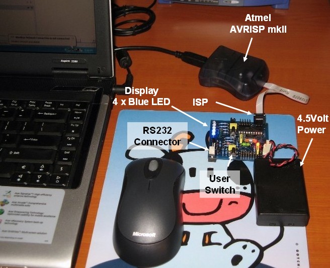
Yeah, I’ve bought this AVRJazz Tiny2313 development board and the AVRIS mkII programmers from ermicro shop. I think this board is suitable for starting my journey on the AVR microcontroller families.
Susan:
Hey, this development board looks cool; it has the 4 blue LEDs, user switch and the RS232 level shifting output, so we could connect it directly to the PC COM port.
David:
Are you free this afternoon; I’m really excited to test this new board and continuing our learning on the AVR microcontroller assembler language.
Susan:
Yeah let’s find a nice place to continue learning this AVR assembler language.
David:
I think I can talk to Timothy my good buddy; he is a micro lab’s assistance to let us use one of the lab’s class rooms.
Susan:
Good idea! (…They went to the micro lab’s class and it’s seem he talked with someone and they both came toward her)
David:
Susan this is Timothy; Timothy this is Susan my friend and my AVR coach as well.
Timothy:
Susan nice to meet you; I’ve heard a lot of you from David; I’ve told David many times ago to start learned this assembler language; but now it’s look like he finally found a smart and pretty personal tutor.
Susan:
(In order to cover the blushed on her face; she just left them and rushed toward the empty class room; while they still smiled on her)…Ok shall we back to our business now?
Timothy:
You’ve heard her David! Let’s start it (…and they both followed Susan into the class room).
David:
Ok, So far I’ve learned to use the AVR Visual Studio 4 for building and debugging the AVR assembler language now it’s time to put the code inside this AVRJazz Tiny2313 board.
Susan:
Most of microcontroller today has the feature for in circuit system programming or ISP for short; this means we could program the microcontroller even though it has been mounted on the production board. This feature makes upgrading the program easier, for example if we want to fix the bugs or add some new features on the board. Now let’s find this ISP on this board, usually for standard Atmel AVR it’s come in the 6 pins (2×3) for newest board or 10 pins (2×5) for the old one.
David:
I’ve got this 2×3 pin that labeled ISP on the board.
Susan:
What is the board crystal frequency?
David:
It’s 11.059200 Mhz
Susan:
I’ve to add the frequency assembler directive statement to our code as follow:
; Program       : myfirstasm.asm
; Description   : Lessons 1: Starting Assembler Program
; Last Updated  : 22  September 2008
; Author        : Susan
.include "tn2313def.inc"
; The AVRJazz Tiny2313 Frequency Clock
.equ F_CPU = 11059200
; Start on the flash ram's address 0
.org 0
main:  ldi  R16,9
       ldi  R17,6
       add  R17,R16
       ldi  R18,255
       out  DDRB,R18
       out  PORTB,R17
       rjmp main
Timothy:
The .equ F_CPU statement simply tells the AVR assembler to use this value as the AVR microcontroller default frequency clock. Now we have to rebuild the program by pressing F7 or from menu Build -> Build.
Susan:
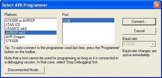
Ok let’s hook up the Atmel AVRISP mkII programmer and switch on the board. From the AVR Studio 4 menu Tools -> Program AVR -> Connect… it will show us the AVR programmer selection as follow:
Select the AVRISP mkII platform and USB for the port then click the Connect button.
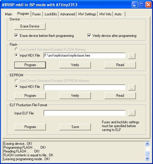
Select program tab and myfirstasm.hex file from f:\avr directory and then click the Program button; now the programmer will start download the HEX code into the Microcontroller. If everything is ok then it will give a message that programming the flash is Ok.
David:
Wow now it’s run on the AVR microcontroller and It show exactly the same output as we run it on the simulator before.
Susan:
I think to make the program a little bit more interesting I will put some more code on it. What’s your opinion Timothy?
Timothy:
Let’s put just a counter start from 0 to 15 and display it on the LED attached to the PORTB.
Susan:
Ok, I will put some delay so we could see the process otherwise the process is just to fast for our eyes. Hmm,… let’s see… I’ll write down the code as follow:
; Program       : myfirstasm.asm
; Description   : Lessons 2: The Counter and Delay
; Last Updated  : 23  September 2008
; Author        : Susan
.include "tn2313def.inc"
; The AVRJazz Tiny2313 Frequency Clock
.equ F_CPU = 11059200
; Start on the flash ram's address 0
.org 0
main:    ldi R24,RAMEND    ; Initial Stack Pointer to SRAM END address (RAMEND)
         out SPL,R24       ; Stack Pointer (SP) = RAMEND

         ldi   R16,9
         ldi   R17,6
         add   R17,R16
         ldi   R18,255
         out   DDRB,R18
         out   PORTB,R17
; Start the additional counter program here
         clr   R18        ; R18 hold the counter value, clear it
loop:    out   PORTB,R18  ; Put on PORTB
         rcall delay_func ; Call delay function
         inc   R18        ; Increase R18 value
         cpi   R18,16     ; Compare R18 with 16
         brne  loop       ; if (R18 != 16) goto loop label
         rjmp  main       ; Goto main label
; Simple Delay Function

delay_func:
         ldi   R19,10     ; R19 = 10
delay0:  ldi   R20,255    ; R20 = 255
delay1:  ldi   R21,255    ; R21 = 255
delay2:  dec   R21        ; Decrease R21 value
         brne  delay2     ; if (R20 != 0) goto delay2 label
         dec   R20        ; Decrease R20 value
         brne  delay1     ; if (R20 != 0) goto delay1 label
         dec   R19        ; Decrease R19 value
         brne  delay0     ; if (R19 != 0) goto delay0 label
         ret              ; Return to the caller
David:
Now the code looks more complex, but by writing the remarks as you did; it makes easier for me to understand the code.
Susan:
Yeah that’s the idea by putting a clear remark to the code, it will easier for programmer to analyze it later on. Ok Timothy now it’s your turn to explain this code to David
Timothy:
Basically Susan just leaves the first program unchanged and adding a couple of new codes for the counter program. From ATtiny2313 Instruction Set Summary datasheet starting on page 217; all of the new statements or mnemonics have their own meaning and you have to pay special attention on the Operation and the Flags columns.
David:
What actually this flag means; I see the Z, C, N, V and H characters.
Timothy:
The FLAG is a special register in AVR microcontroller called Status Register or SREG for short; see page 10 and 11 on the datasheet
The letter Z, C, N, V and H are the bit’s name in SREG register; All of these bits in the SREG register is effected by the ALU (arithmetic logical unit) operation. For example I will use the command compare register with immediate constant (cpi) and followed by the statement branch not equal (brne) as the example code above:
cpi   R18,16     ; Compare R18 with 16
brne  loop       ; if (R18 != 16) goto loop label
According to the Instruction Set Summary tables; this command will effecting the SREG register by changing the bits of Z, C, N, V and H. The brne command depend on the Z bit in SREG status register. If this bit is cleared which is “0”, means R18 is not equal to 16 then the brne command will instruct the microcontroller to jump to the loop label.
Susan:
Every ALU operation that resulting zero on the general purpose registers always set this Z bit in SREG register. That’s why this bit named Zero or Z for short.
David:
Ok, that also explained the delay function from the example codes:
         ldi   R21,255    ; R21 = 255
delay2:  dec   R21        ; Decrease R21
         brne  delay2     ; if (R20 != 0) goto delay2 label
         dec   R20        ; Decrease R20 value
as long as the result of dec R21 command is greater than zero, the Z bit always clear (0) and the brne command will continue loop to delay2 label, but when it reach zero than the Z bit will be set (1); the brne command will check the Z bit and because this bit is set then it will continue to the next command which is dec R20.
Timothy:
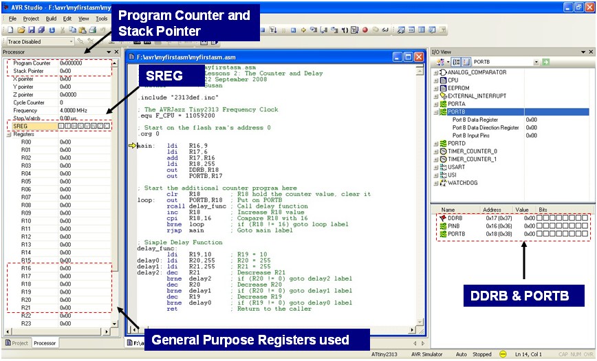
That exactly how it works, it will be more clear when you do the debugging process on these codes and pay special attention to the SREG register and the general purpose registers as you run through this code inside the AVR Studio 4.
Susan:
The other two command rcall (relative call) and ret (return) are dealing with the calling of program function and returning from it; same like calling and returning procedure/function on the higher level language. When rcall command is executed by microcontroller the return address of the next command after rcall which is inc R18 in our example will be stored onto the stack; and when the microcontroller execute the ret command it will load the return address from stack and start execute from there.
David:
What did you mean by the stack?
Susan:
The stack is the special location usually it start at the last address of SRAM (static ram) memory inside the microcontroller. On the Atmel AVR Tiny2313 microcontroller the size of this SRAM is 128 bytes; therefore before using it we have to initialized the stack pointer to point to the last address of the SRAM (RAMEND) as you see from out SPL,R24 statement. You can watch this stack memory while you debugging the code
David:
Guys, I think today lesson is enough for me; I will debug or simulating this code and slowly try to have better understanding on this codes by my self; after that I will download the HEX code into the board.
Timothy:
While you learn these codes; there is a good application note from Atmel titled AVR Instruction Set; try to search and download it from their site. This application note will explained in more detail every assembler instruction on the AVR microcontroller family.
David:
Thanks guys we will continue learning this AVR assembler language next time, but from now on; how about coffee time at the starbuck near here and this time on my treat!
Susan:
I would like to.
Timothy:
What are we waiting for, let’s go.
Bookmarks and Share


Comment by Inna.
Hello,I need to write a delay function in avr assembler with two or more registers. In my algorithm I need to have a formula with those registers and by changing those registers I must have any delay(sec) I want. I am new and I really don’t have an idea how to do that. Can anybody give me a hint?