Blog Entry
Quick and Efficiently Wiring Your Prototype Circuit Board
February 2, 2011 by rwb, under Yet Another Tips.
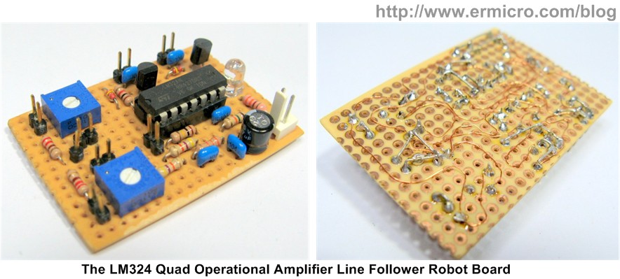
Many times we need to quick wiring the electronic circuit on the prototype board (perforator board). One of the problems wiring this kind of prototyping board using the ordinary wire (PTFE insulated wire) is it become difficult and looks clumsy when the electronic circuit become complex, especially if we want to rewire the same terminal more than once. Now take a look at this prototype board wiring method used in “LM324 Op-Amp Line Follower Robot with Pulse Width Modulation” article on this blog.
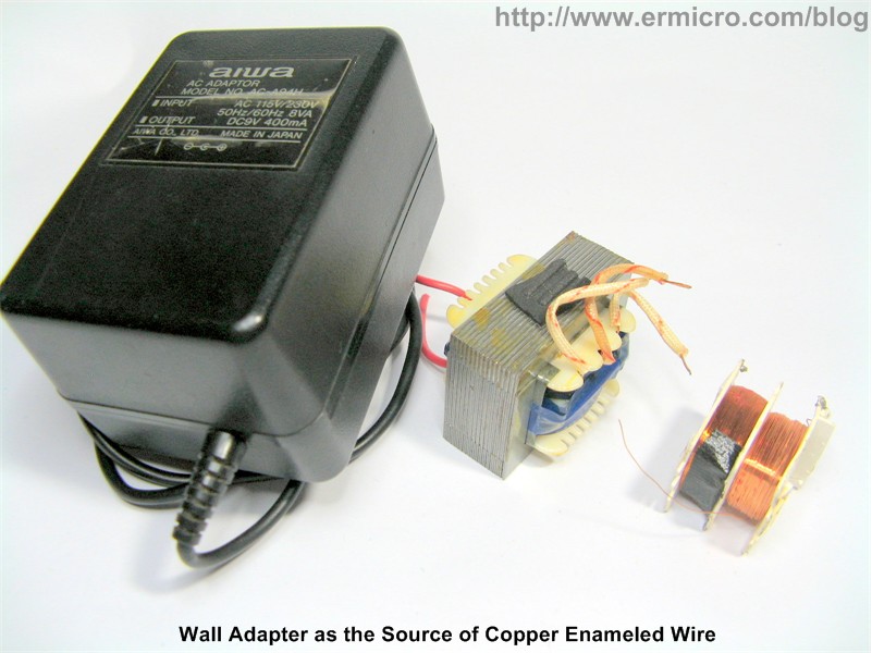
From the above picture you could see that I used the copper enameled wire that you could easily found in many discarded electrical transformator. You could use any enameled copper with the AWG (American Wage Gauge) number 25 to 30 (0.45466 mm to 0.254 mm) for wiring your board. Any non switching 250mA to 1000mA discarded wall adapter transformator are a good candidate for the copper enameled wire sources or you could buy it on your local electric/electronic store.
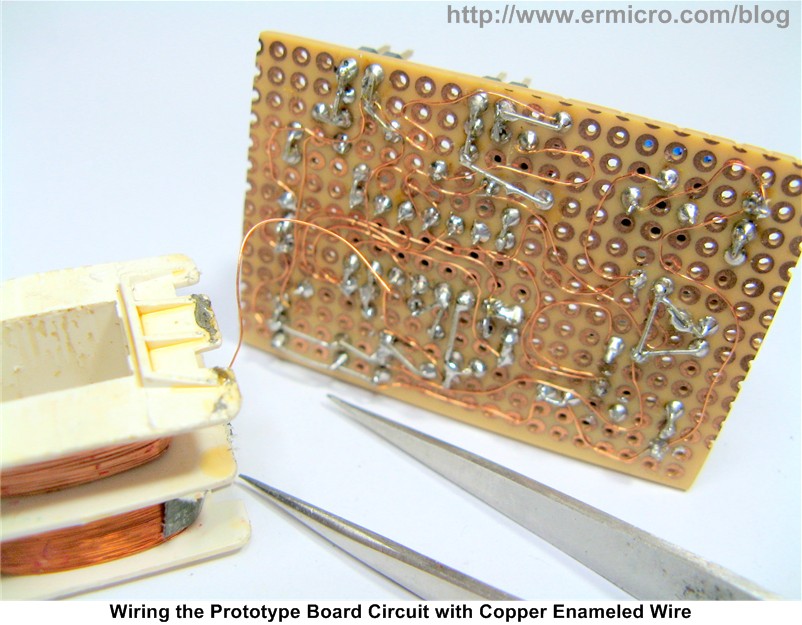
Before applying solder thin on this wire, you need to remove the enameled layer at the soldering point with the utility knife and use tweezers to place the wire on the board. You could also use the glue gun and apply small amount of it to the enameled wire group to make them stiffer and stable.
Using this wiring method you could easily populate more electronics components in relatively small prototype board and opening the possibility to hand wiring the surface mount components (SMC) such as the TQFP (Thin Quad Flat Pack) and SOIC (Small Out-Line Integrated Circuit) which is found in many microcontroller package. Hoping this tip could help you prototype your own project quickly and efficiently… Happy wiring…
Bookmarks and Share


Related Posts
5 Responses to “Quick and Efficiently Wiring Your Prototype Circuit Board”
Comment by rwb.
Yes, some new type of this copper coated layer (enameled) will burn during soldering. But I prefer this old type i.e. the enameled must be removed manually so we could prevent short circuit on the copper wire stack in the circuit when we accidentally touch them with the soldering iron, especially in very dense wiring. Actually removing the enameled is easy especially on very small copper wire diameter (e.g 0.3 mm) as it only need two or three time scratch from the utility knife or you could use the screwdriver tip in order to remove the coated layer.
Comment by 691175002.
I have never used a PIC before in my life but I went from nothing to completing my project in an evening just by reading your blog.
My previous electronics experience was just lighting up LEDs with an arduino so it was a non-trivial leap.
For the curious I used a 12F683 to control the lighting on a model plane. My transmitter outputs switch positions as a bunch of PWM signals which I convert into varying brightnesses and flashing patterns making my plane officially the most pimp plane ever.
Thanks, I wasn’t even sure if I would be able to learn how to program for a pic before finding your site.


Comment by trygvis.
Do you know of any wires that you don’t have to remove the enameled layer from? I know there are some types with such thin layer of insulation that it’ll burn right off at 300 degrees.