Blog Entry
Beginners AVR Assembler Language Programming 2
November 25, 2008 by rwb, under Microcontroller.
From her house’s window, she could see David holding his notebook walking across the street towards her house. She runs down the stair to open the door (click here for first tutorial)
David:
Hi… sorry for being late, I’ve had trouble downloaded the Atmel AVR Studio 4 and the ATtiny 2313 microcontroller datasheet as you asked me yesterday; You know it’s seem my internet provider always has a problem when I need it most.
Susan:
Did you manage to download it, because this is very important if you want to code in AVR microcontroller’s assembler language you must have this tools and the datasheet near you.
David:
Yeah, I went to the free hotspot at the mall near here and download it.
Susan:
Ok… let’s continue our AVR assembler language microcontroller programming lesson; I like to begin first with the registers. The microcontroller’s register actually is the special memory inside the microcontroller that functioning similar to the control panel. You just imagine the control panel with the switches and the indicator lamps. Whatever you want the microcontroller to do something, you just turn on or turn off some of these switches on the panel.
David:
It’s seems like operating my DVD player; if I want to play a movie, I just press the play button.
Susan:
The idea it similar, but this sophisticated AVR microcontroller registers contain more then just one switch. The ATtiny2313 is 8-bit microcontroller this mean this microcontroller process the data in the 8-bit form. Now take a look on the registers summary of the AVR ATtiny2313 microcontroller datasheet on page 215.
David:
It looks quite a lot of registers there; but all of registers is 8-bit wide and they also have a funny name. Do I have to remember all of these names?
Susan:
No you don’t by the time you become acquainted with this AVR microcontroller than automatically you will remember the names and their functions. Another type of registers are called general purpose registers see datasheet on page 9 and 12; these registers is directly connected to the microcontroller’s ALU (Arithmetic Logical Unit), so it can be used to perform these following tasks:
1. Arithmetic operation e.g. adding (ADD) and subtract (SUB)
2. Logical operation e.g. AND and OR
3. Bit function operation e.g. set bit(s) register (SBR) and clear bit(s) register (CBR)
David:
So what is the different between the first register you’ve mentioned and the general purpose registers.
Susan:
The first register on the page 215 (Atmel datasheet 2543I–AVR–04/06) is called instruction registers; while the general purpose register is used for ALU arithmetic, logical and bit functions operation and there are 32 general purpose registers see the datasheet on page 12; named R0 to R31.
For example if you want to instruct AVR microcontroller to add the number 9 and 6, than you have to do this in the general purpose registers; and if you want to present the result which is 15 to the outside world than you have to use the instruction registers.
David:
Ok… can we do this example first before I’m getting more confused.
Susan:
First I’ll write down the instruction on the paper so I could explain this code straightforward to you, later on we will put this code to the Atmel AVR Studio 4:
LDI R16,9
LDI R17,6
ADD R17,R16

LDI R18,255
OUT DDRB,R18
OUT PORTB,R17
The LDI, ADD and OUT command is called mnemonic; this is the syntax of assembler language in the form of human language. The LDI mean “load immediate“, therefore the command LDI R16,9 means load immediately a constant number 9 to the general purpose register named R16.
David:
Why you use R16 instead of R0, is it easier to remember always start with R0, R1 and so on.
Susan:
Good question; this is because the AVR microcontroller general purpose registers from R0 to R15 could not be used for loading a constant directly; the load immediate (LDI) statement only works for registers R16 to R31
David:
Ok… I understand now, It’s seems this general purpose registers similar to the variables in high level language such as assigning the constant to the variable in C language:
unsigned char myvar1,myvar2;
myvar1 = 9;
myvar2 = 6;
or if I write down in BASIC language:
dim myvar1,myvar2
myvar1 = 9
myvar2 = 6
Susan:
Now you’ll see the similarity between assembler language and high level language; in the high level language we don’t care about where the compiler will put our variables; but in assembler we as programmer that make the decision where to put our constant. Ok let’s move on to the ADD R17,R16 statement, this statement just simply adding the value of register R16 to the existing value of register R17; now the value of register R17 should be 15.
David:
For my own reference I will write down this assembler statement in the form of C language statement:
unsigned char myvar1,myvar2;
myvar1 = 9;                // LDI R16,9
myvar2 = 6;                // LDI R17,6
myvar2 = myvar2 + myvar1;  // ADD R17,R16
Susan:
You seem to be making a progress now; some of the assembler programmers put the equivalent C syntax as the comment for their assembler program; this give them a clear picture of what the program do. The next three statements involving the AVR microcontroller I/O (input/output) instruction registers.
The AVR ATtiny2313’s have 18 programmable I/O lines; all of these I/O registers is a bidirectional I/O and it only can work one direction at a time. In order to control which direction of this I/O to be used, we have to set the data direction register for the Port B.
David:
This data direction register sounds like the three state bidirectional bus logic to me that allow data to move only one direction at the time.
Susan:
Yeah, you’ll right on page 50 (Atmel datasheet 2543I–AVR–04/06) of the ATtiny2313 datasheet you could see the schematic and the detail explanation of these I/O port. Therefore to enable each of this PORT B bits as an output we have to put the logic one to all the PORT B data direction register named DDRB bits as follow:
LDI R18,255
OUT DDRB,R18
The 255 value is equivalent to “1111 1111” in binary or “FF” in hexadecimal number.
David:
Why you have to use the R18; why not just directly assign the value 255 to the DDRB?
Susan:
There is no such statement in the AVR microcontroller assembler; the only way to put the value to the DDRB is through the general purpose register using the OUT statement and this also valid for the PORT B. On our last example program statement; we assign the R17 value to the Port B:
OUT PORTB,R17
Of course in C; we can assign the value to this direction register directly; that’s the job of the C compiler to convert it as we’ve done in assembler. Therefore the complete C equivalent syntax for your reference is
unsigned char myvar1,myvar2;
myvar1 = 9;                // LDI R16,9
myvar2 = 6;                // LDI R17,6
myvar2 = myvar2 + myvar1;  // ADD R17,R16
DDRB = 255;                // LDI R18,255 + OUT DDRB,R18
PORTB = myvar2;            // OUT PORTB,R17
David:
Ok… let’s put the code into the Atmel AVR Studio 4.
Susan:
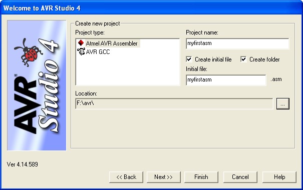
When you first start the Atmel AVR Studio 4 it will show you the Project Wizard window, choose the new project button and It will prompt you to enter the Project type, Project name and the Project location:
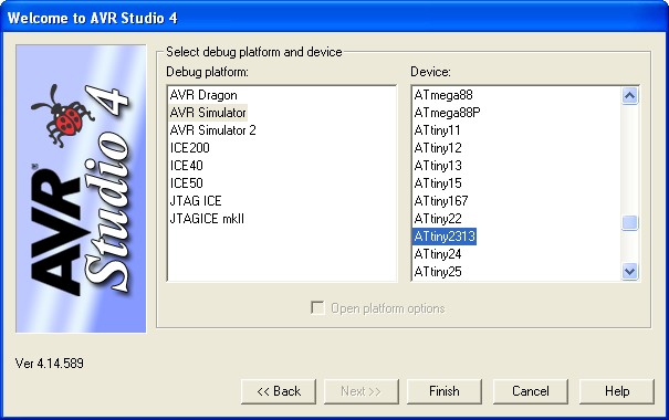
I Choose Atmel AVR Assembler for Project Type and myfirstasm as the Project name; and for the project location; I use the f:\avr directory. Press the Next button and the project wizard will show you the debug platform and device window:
We use the AVR Simulator as the debugging tools and select ATtiny2313 from the device. Then press the Finish button.
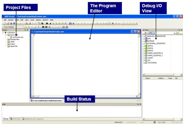
This will bring you to the Atmel AVR Studio 4 IDE (integrated development environment). Now I will write down our first example code to the program editor as follow:
; Program         : myfirstasm.asm
; Description     : Lessons 1: Starting Assembler Program
; Last Updated    : 22  September 2008
; Author          : Susan
.include "tn2313def.inc"
; Start on the flash ram's address 0
.org 0
main: ldi  R16,9
      ldi  R17,6
      add  R17,R16
      ldi  R18,255
      out  DDRB,R18
      out  PORTB,R17
      rjmp main
David:
It’s seems you put a few new strange statement and my guess is the “;” sign is the comment mark for assembler language similar to C “//” or “/* */” marks.
Susan:
The .include and .org statement is called a compiler directive; this is not the assembler language statement. This first statement is to instruct the compiler to include the ATtiny2313 definition library which you can found in c:\Program Files\Atmel\AVR Tools\AvrAssembler\Appnotes directory when compiling the code. The .org or originate statement is to instruct the compiler to put the code on AVR flash ram address 0 when compiling the code.
The rjmp is a relative jump instruction; this assembler statement simply tells the microcontroller program pointer to jump or pointing to the label main. This makes our program to always repeating this code forever.
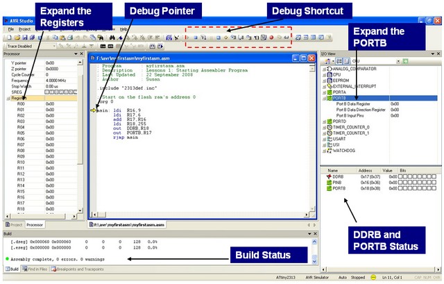
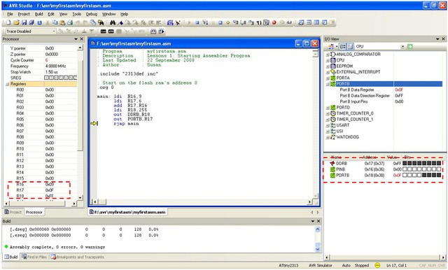
Now let’s build and start debugging the code. On the menu Build -> Build or Press F7 to compile the code and start debugging from menu Debug -> Start Debugging.
David:
Wow… this debugging facility on the Atmel AVR Studio 4 it’s very useful and informative; this means I could run and test the code even though there is no physical AVR microcontroller hardware.
Susan:
That’s right; it’s also a good practice for all the microcontroller’s programmers to first debug their code before flashing it into the microcontroller. Now to continue execute the code we just use Step Into command; from menu Debug -> Step Into or press F11 repeatedly while watching the Registers status and the PORT B status windows.
David:
Ok, I think up to this point I’ve learned the basic Atmel AVR assembler language and how to use the AVR Studio 4 for building and debugging the code. Now it’s time to put it on the real hardware. What is your suggestion Susan?
Susan:
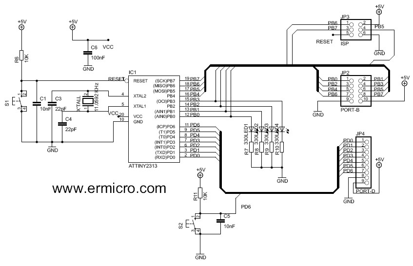
First you have to build the basic AVR microcontroller ATtiny2313 hardware and find a good AVR programmer; which enable you to transfer the code created by AVR Studio 4 into the microcontroller. My suggestion is to use the Atmel AVRISP mkII for AVR programmer; because this programmer is fully integrated in AVR Studio 4 and can be used to program almost all the Atmel AVR microcontroller’s family. For the basic AVR ATtiny2313 hardware; you could use this following schematic:
David:
Thanks Susan; I’ll try to find the programmer and build this hardware first before we continue learning this AVR assembler language. Anyway are you free this Friday for a dinner?
Susan:
Is a date?
David:
Yes, will you? Please…
Susan:
Ok, I’ll see you on Friday
David:
Bye Susan and thanks for your time
(Beginners AVR Assembler Lanuage Programming 3)
Bookmarks and Share


Related Posts
3 Responses to “Beginners AVR Assembler Language Programming 2”
Comment by spw.
This is awesome! Huge thanks!

Comment by willprice94.
I hate to be a pedant but a few mistakes:
“Now take a look on the registers summary of the AVR ATtiny2313 microcontroller datasheet on page 215”
I found it on page 211
“Ok… can we do this example first before I’m getting more confuse.”
confused
“You’ve seem making a progress now”
should be “You seem to be making progress now”
“This data direction register is sound like the three state”
*data direction register sounds like…
“and my guessed the “;” sign is the comment mark”
*and my guess is the “;”
“Another type of registers is called general purpose registers”
‘is’ should be ‘are’?
I just think they should be corrected to make this exceptional article even better. I love the format and the equivalent in C, it makes it MUCH easier to understand. Thank you so much for doing this, I’m thoroughly enjoying the series so far, I look forward to the next installment!
Keep up the work!
Regards,
Will