Blog Entry
Basic Resistor Circuit
November 19, 2008 by rwb, under Electronics.
Resistor basically is used as a current limiter or current/voltage divider in electronics circuit. Resistor value is measured in Ohm (Ω) name after George Simon Ohm who first to lay down the fundamental relationship among Resistance, Current and Voltage. This relationship is known as Ohm’s law; basically the Ohm’s law say that the current flow in the closed circuit is equal to the voltage divided by the total resistance occur in the circuit or we can write the Ohm’s law equation as follow:
I = V /R
Where I is the current measured in Ampere, V is the voltage measured in Volt and R is the resistance measured in Ohm. Another important law that works closely with the Ohm’s law is known as Kirchhoff’s law (first introduced by Gustav R. Kirchhoff). We will show you the practical used of these two laws as we travel through this blog.
Voltage Divider:
Now let’s examine this simple closed circuit bellow (Figure 1A):
Assuming that we are using 5 volt battery and 4700 (4K7) ohm resistor; according to Ohm’s law, the amount of current flowing in the circuit is:
I = V / R = 5 / 4700 = 0.00106 Ampere
If we add another 4700 (4K7) ohm resistor in series (Figure 1B), according to Ohm’s law the amount of current is:
I = V / R = 5 / (4700 + 4700) = 0.00053 Ampere
Now let’s calculate the voltage across each resistor (Figure 1C), base on the Ohm’s law:
V = I x R
V1 = I x R1 = 0.00053 x 4700 = 2.49 Volt
V2 = I x R2 = 0.00053 x 4700 = 2.49 Volt
As you could see from the result, the voltage is divided by these two resistors (R1 and R2). The circuit shown on Figure 1C is known as Voltage Divider Circuit. By substituting the current using the equation from Ohm’s law (I=V/R) on each V1 and V2 equation above; we will get this handy Voltage Divider equation:
The sum of V1 and V2 will be V:
V = V1 + V2 = 2.49 + 2.49 = 5 Volt
Or we could write the same equation by moving the V1 and V2 to the left side:
V – V1 – V2 = 5 – 2.49 – 2.49 = 0 Volt
This is known as Kirchhoff’s voltage law that say the total sum of voltage in the closed circuit is equal to zero. If you look closely many of the electronics circuit design used this basic voltage divider circuit (i.e. transistor biasing, volume control, voltage reference, etc).
Voltage Comparator
Let’s we continue play with this circuit, by adding two more resistors (R3 and R4) in parallel with R1 and R2; we will have this following circuit (Figure 2A):
According to Ohm’s law the current are:
I1 = V / R = 5 / (4700 + 4700) = 0.00053 Ampere
I2 = V / R = 5 / (4700 + 4700) = 0.00053 Ampere
The sum of I1 and I2 is the total current flow on the circuit (I):
I = I1 + I2 = 0.00053 + 0.00053 = 0.00106 Ampere
This is known as Kirchhoff’s current law that say the total current flow in the circuit is the sum of total current flow on each circuit’s nodes (branches). From Figure 2B the Voltage across R2 and R4, base on Ohm’s law are:
V1 = I1 x R2 = 0.00053 x 4700 = 2.49 Volt
V2 = I2 x R4 = 0.00053 x 4700 = 2.49 Volt
So the Voltage different (VD) between V1 and V2 is:
VD = V1 – V2 = 0 Volt
This circuit in figure 2B is used in many comparator circuit the sensor that measure the voltage different; this mean any changes on R1, R2, R3 or R4 value will generate voltage different across V1 and V2.
Digital to Analog Converter
Some practical used of the voltage divider circuit, is to convert the digital signal forms to the analog signal forms. The digital signal is as a signal presented in discrete value (0 volt or 5 volt) while the analog signal is a signal presented in continues value (0 volt to 5 volt). Today the digital to analog converter circuit play an important role in our life such as your MPEG player, PDA and Mobile Phone, all of these gadgets process the signal in digital forms and presenting the output in the analog signal forms; so we could hear and see.
Ok… let’s start examine this following resistor’s circuit:
On Figure 3A we replace the 4K7 resistor as R and 2R (means 2 times the R value), from the voltage divider equation we could calculate the Vout as follow:
Vout = (Rtotal234 / (Rtotal234 + R1)) x V
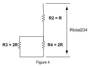
Where Rtotal234 is the total resistances of R2, R3 and R4; R3 and R4 resistors is in parallel and connected in series with R2 resistor (see Figure 4):
Rtotal234 is:
Rtotal234 = ((R3 x R4) / (R3 + R4)) + R2 = ((2R x 2R) / (2R + 2R)) + R = 2R
Put this Rtotal234 value on the equation above, we could calculate the Vout:
Vout = (Rtotal234 / (Rtotal234 + R1)) x V
Vout = 2R / (2R + 2R) x V = 0.5 V
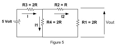
Continue with the next circuit shown on Figure 3B; we make slightly change on the circuit diagram for the purpose of our calculation and we have the same circuit shown on Figure 5:
Using the voltage divider equation:
Vout = (R1 / R1 + R2) x VR4.
Where VR4 is the voltage drop across R4 resistor; again by using the voltage divider equation:
VR4 = (Rtotal124 / (Rtotal124 + R3) x V
Rtotal124 = ((R1 + R2) x R4)/(R1 + R2 + R4)
Rtotal124 = 3R x 2R / 5R = 6/5 R
VR4 = (Rtotal124 / (Rtotal124 + R3) x V
VR4 = 6/5R / (6/5R + 2R) x V
VR4 = 3/8 V
By putting all this things together, we could calculate the Vout as follow:
Vout = (R1 / R1 + R2) x VR4
Vout = (2R/2R + R) x 3/8V
Vout = 2/3 x 3/8 V = 0.25 V
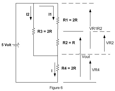
Wheew… only one last circuit to be calculated; again we change the circuit appearance on Figure 3C to the circuit shown on Figure 6:
From the Kirchhoff’s voltage law and applying the voltage divider equation we get this following calculation:
Vout = VR4 + VR2
VR4 = R4 / (Rtotal123 + R4) x V
VR1R2 = V – VR4
VR2 = R2 / (R1 + R2) x VR1R2
Rtotal123 is the total resistance of R1 series with R2 and both parallel with R3:
Rtotal123 = R3 x (R1 + R2) / R3 + R1 + R2
Rtotal123 = 2R x 3R / 5R = 6/5 R
VR4 = R4 / (Rtotal123 + R4) x V
VR4 = 2R / (6/5R + 2R) x V
VR4 = 5/8 V
VR1R2 = V – 5/8V = 3/8V
VR2 = R2 / (R1 + R2) x VR1R2
VR2 = 1/3 x 3/8V
VR2 = 1/8 V
By adding VR2 and VR4 value we get the Vout = 5/8 V + 1/8 V = 6/8 V = 0.75 V.
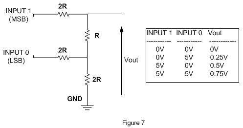
The circuit shown on Figure 3 is known as 2 bit R-2R ladder; by changing the combination of these 2 bits digital input (i.e. 0 Volt or 5 Volt) we could get 4 combination of output as shown on Figure 7:
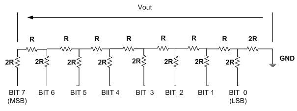
Using two bits analog to digital converter we could get 4 steps of analog output by increasing the number of input to 8 bits we could get 256 combination of analog output as shown on this following 8bit R-2R ladder circuit:
Current Limiter
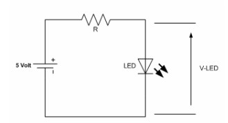
On the last example we will use resistor as a current limiter to limit the current flow on the LED (Light Emitting Diode):
Most of LED will operate safely on the voltage of 2 Volt with 15mA (0.015 Ampere) current flow on it. To calculate the resistor value, first we have to calculate the voltage across resistor (V-Resistor):
V-Resistor = V – V-LED = 5 – 2 = 3 Volt
Now the resistor value according to Ohm’s law is:
R = V / I = 3 / 0.015 = 200 Ohm
We could use the nearest higher value available on the market; 220 Ohm. The other thing to be considered is to calculate the power dissipation (power lost as heat) in resistor using this power equation:
P = V x I
P is the power measured in Watt, I is the current measured in Ampere, V is the voltage measured in Volt; the power dissipated in resistor with voltage of 3 Volt and 0.015 A current flow on it is:
P = V x I = 3 x 0.015 = 0.045 Watt
So we could use the 0.25 Watt resistor available on market to our circuit.
Bookmarks and Share



Comment by diaaeldin.
think you